
Display module lighting test device and method

A technology for displaying modules and testing devices, which is applied in the direction of measuring devices, electronic circuit testing, measuring electricity, etc. It can solve the problems of affecting the progress of module testing and high cost, so as to reduce the design of peripheral circuits, reduce the number of uses, and simplify hardware parts Effect

Active Publication Date: 2019-07-12
WUHAN CHINA STAR OPTOELECTRONICS TECH CO LTD
View PDF7 Cites 0 Cited by
  • Summary
  • Abstract
  • Description
  • Claims
  • Application Information

AI Technical Summary

Problems solved by technology

These related tests require a module lighting test platform to be implemented. The lighting test devices used by most small-size panel manufacturers have a large number of components and relatively high costs, and are likely to affect the progress of module testing.

Method used


Image

  • Display module lighting test device and method
  • Display module lighting test device and method
  • Display module lighting test device and method

Examples


Embodiment Construction

[0020] The following structural drawings and embodiments describe the present invention in detail.

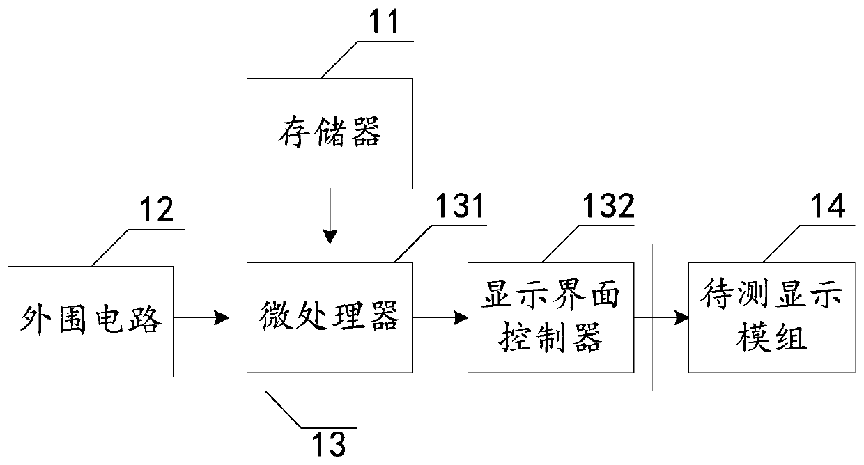
[0021] see figure 1 , figure 1 It is a structural schematic diagram of an embodiment of the display module lighting test device of the present invention. It should be understood that the specific embodiments described here are only used to explain the present invention, and are not intended to limit the present invention.

[0022] In this embodiment, the display module lighting test device is used for performing a lighting test on the display module to be tested. The display module lighting test device 10 includes: a memory 11 , a peripheral circuit 12 , and a field programmable gate array chip 13 . Wherein, the field programmable gate array chip 13 includes: a microprocessor 131 and a display interface controller 132 .

[0023] Wherein, the field programmable gate array chip 13 is connected with the memory 11 and the peripheral circuit 12 respectively. Specifically, a micr...


PUM


Abstract

The invention discloses a display module light-on test device and a display module light-on test method. The device is used for performing light-on test on a to-be-tested display module and comprises a memorizer, a peripheral circuit and a field programmable gate array chip, wherein a microprocessor and a display interface controller are integrated in the field programmable gate array chip; the microprocessor is used for outputting initialization information; the microprocessor is connected with the display interface controller; and the field programmable gate array chip is connected with the to-be-tested display module through the display interface controller to output the initialization information to the to-be-tested display module, so that the to-be-tested display module is subjected to initialization operation, processed picture data is output to the to-be-tested display module, and the to-be-tested display module is subjected to light-on test. By the method, a hardware part of the light-on test device can be simplified, the design of the peripheral circuit is reduced, the use amount of electronic components is reduced, the stability of the light-on device is improved and maintenance of research staff is facilitated.

Description

technical field [0001] The invention relates to the display field, in particular to a display module lighting test device and method. Background technique [0002] At present, small-size panel manufacturers will conduct corresponding functional tests on the mobile phone module after the mobile phone panel is assembled, such as the quality of the module optics, the overall power consumption of the module, and gamma debugging. These related tests require a module lighting test platform to be implemented. Most small-size panel manufacturers use a large number of components in the lighting test device, which is relatively expensive and easily affects the progress of module testing. Contents of the invention [0003] The technical problem mainly solved by the present invention is to provide a display module lighting test device and method, which can simplify the hardware part of the lighting test device, reduce peripheral circuit design, reduce the number of electronic componen...

Claims


Application Information

Patent Timeline
Patent Type & Authority Patents(China)
IPC IPC(8): G01R31/28G05B19/042
CPCG01R31/282G05B19/0428G05B2219/2604
Inventor 安泰生
Owner WUHAN CHINA STAR OPTOELECTRONICS TECH CO LTD
Learn More