
Measurement method of transient transverse friction coefficient of rolling contact point based on optical fiber gratings

A fiber grating and rolling contact technology, which is applied to measuring devices, instruments, and mechanical devices, can solve problems such as the inability to achieve accurate measurement and the inability to distinguish changes in Bragg wavelengths, and achieve the effect of solving cross-sensitivity problems

Active Publication Date: 2017-05-31
WUHAN UNIV OF TECH
View PDF5 Cites 5 Cited by
  • Summary
  • Abstract
  • Description
  • Claims
  • Application Information

AI Technical Summary

Problems solved by technology

[0004] The technical problem to be solved by the present invention is to provide an optical fiber based Measuring method and device for transient lateral friction coefficient of rolling contact point of grating

Method used


Image

  • Measurement method of transient transverse friction coefficient of rolling contact point based on optical fiber gratings
  • Measurement method of transient transverse friction coefficient of rolling contact point based on optical fiber gratings
  • Measurement method of transient transverse friction coefficient of rolling contact point based on optical fiber gratings

Examples


Embodiment Construction

[0031] In order to make the object, technical solution and advantages of the present invention clearer, the present invention will be further described in detail below in conjunction with the accompanying drawings and embodiments. It should be understood that the specific embodiments described here are only used to explain the present invention, not to limit the present invention.

[0032] 1. Experimental principle

[0033] Fiber Bragg grating sensor is a new type of fiber optic sensor made by utilizing the sensitivity of Bragg wavelength to temperature and strain. According to the fiber-coupled mode theory, when broadband light is transmitted in a fiber grating, mode coupling will occur, and the light satisfying the Bragg condition will be reflected. The central reflection wavelength of the fiber Bragg grating (FBG) is:

[0034] lambda B =2n eff ·Λ (1)

[0035] In the formula, n eff is the effective refractive index of the guided mode, and Λ is the grating period.

[00...


PUM


Abstract

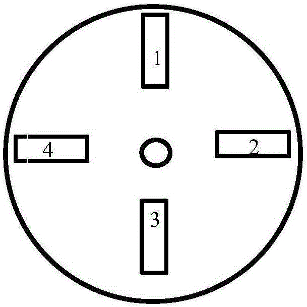
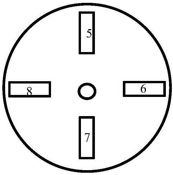
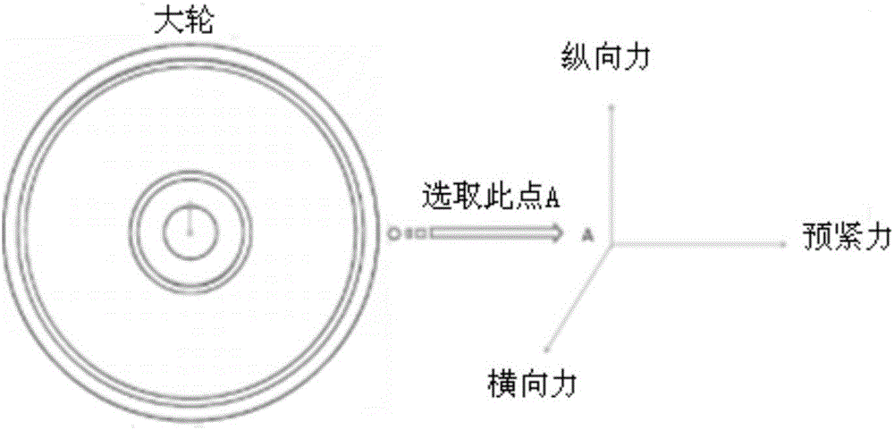
The invention discloses a measurement method of a transient transverse friction coefficient of a rolling contact point based on optical fiber gratings. The measurement method comprises the following steps of symmetrically pasting the optical fiber gratings with different central wavelengths on the two sides of a big wheel, sequentially marking the optical fiber gratings, adjusting a certain normal force generated by the big wheel and a small wheel at the rolling contact point, forming a certain attack angle between the big wheel and the small wheel to allow the big wheel to generate a certain transverse force at the rolling contact point, controlling the rotating speed of the big wheel, transmitting a strain signal generated by the big wheel to the optical fiber gratings when the big wheel rotates, transmitting a built-in light source of a demodulator to the optical fiber gratings via an optical fiber grating rotary connector, allowing the optical fiber gratings to generate strain signals, demodulating the strain signals of the optical fiber gratings with the demodulator, transmitting demodulated signals to an industrial personnel computer, allowing the industrial personnel computer to acquire and analyze the demodulated signals, and calculating transient positive pressure and friction of the big wheel at the rolling contact point according to wavelength shift of the optical fiber gratings.

Description

technical field [0001] The invention relates to the field of optical fiber grating sensing, in particular to a method and device for measuring the transient lateral friction coefficient of rolling contact points based on optical fiber gratings. Background technique [0002] Fiber Bragg grating sensing technology is developed on the basis of fiber optic sensing technology. The basic principle of fiber Bragg grating sensing system is to connect multiple gratings (each with a different central wavelength) in series on one optical fiber, and emit The light wave passes through the splitter and passes through all the gratings, and the reflected light is coupled into the fiber grating demodulator through the other interface of the splitter, and the wavelength and its change of the reflected light can be measured by the fiber grating demodulator, and the demodulation can be obtained After analyzing and processing the data, we can get the change amount corresponding to the environmen...

Claims


Application Information

Patent Timeline
IPC IPC(8): G01N19/02G01D21/02
CPCG01D21/02G01N19/02
Inventor 刘晓刚谭跃刚
Owner WUHAN UNIV OF TECH
Learn More