Field calibration system for magnetoelectric sensor

A magnetoelectric sensor and on-site calibration technology, applied in the direction of using electric devices, using electromagnetic means, instruments, etc., can solve the problem that it cannot be used as a judgment sensor, cannot guarantee the signal-to-noise ratio of high-frequency bands, and has poor anti-interference ability in high-frequency parts and other problems, to achieve the effect of simple structure, elimination of calibration error, and convenient portability

Active Publication Date: 2017-05-31
匙庆磊
View PDF9 Cites 2 Cited by
  • Summary
  • Abstract
  • Description
  • Claims
  • Application Information

AI Technical Summary

Problems solved by technology

[0003] 1. The anti-interference ability of the high-frequency part is poor. No matter whether the step signal or the unit pulse signal is used, the signal-to-noise ratio of the high-frequency band cannot be guaranteed, and it is only suitable for long-term calibration;
[0004] 2. When traditionally using sinusoidal signals for calibration, although the input signal can be adjusted to ensure the signal-to-noise ratio in the high-frequency band, the error of the actual test results in the high-frequency band can reach 30%, which cannot be used as a basis for judging whether the sensor is damaged;
[0005] 3. White noise and pseudo-random binary signals have strong anti-interference, but need to know the frequency characteristic or transfer function of the sensor to complete the convolution operation

Method used


Image

  • Field calibration system for magnetoelectric sensor
  • Field calibration system for magnetoelectric sensor
  • Field calibration system for magnetoelectric sensor

Examples


Embodiment Construction

[0025] The present invention will be described in further detail below in conjunction with the examples and the accompanying drawings, but the embodiments of the present invention are not limited thereto.

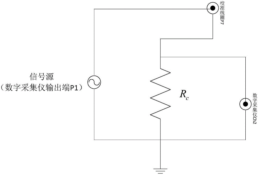
[0026] see figure 1 , which is a connection block diagram of the magnetoelectric sensor calibration system of the present invention.

[0027] The invention provides an on-site calibration system for a magnetoelectric sensor, which includes a digital acquisition instrument 1, a calibration circuit 2, a signal processing device 3 and a magnetoelectric sensor 4 to be calibrated. The digital acquisition instrument 1 is respectively connected with the calibration circuit 2, the magnetoelectric sensor 4 and the signal processing device. The digital acquisition instrument 1 collects the signals of the calibration circuit 2 and the magnetoelectric sensor 4 , sends them to the signal processing device 3 for processing, and finally calculates the electrical sensitivity of the magnet...


PUM


Abstract

The invention provides a field calibration system for a magnetoelectric sensor. The field calibration system for the magnetoelectric sensor comprises a digital acquisition device, a calibration circuit and a signal processing device; the digital acquisition device is provided with a voltage signal output end, a first signal input end and a second signal input end; the calibration circuit is provided with an excitation signal output end and a calibration signal output end; a voltage signal output end of the digital acquisition device is used for being connected with the excitation signal output end of the calibration circuit; the excitation signal output end of the calibration circuit is used for being connected with a magnetoelectric sensor to be calibrated; the calibration signal output end of the calibration circuit is connected with a first signal input end of the digital acquisition device; a second signal input end of the digital acquisition device is used for being connected with the magnetoelectric sensor to be calibrated and receiving vibration signals of the magnetoelectric sensor; the signal processing device is connected with the digital acquisition device, and is used for receiving two paths of signals from the digital acquisition device.

Description

technical field [0001] The invention relates to the field of vibration measurement calibration, in particular to a magnetoelectric sensor calibration system. Background technique [0002] In the field of earthquake detection and engineering vibration measurement, a large number of vibration measurement sensors are often required for long-term monitoring of the ground, engineering structures, and mechanical equipment. For example, in terms of strong earthquake observation, there are more than 30,000 sets of data used for earthquake observation worldwide, and the sensors deployed in structural health monitoring and environmental vibration monitoring are much higher than this number, and these sensors often have to work continuously for several years. Therefore, its on-site calibration technology has a large number of practical needs. The currently existing technologies that can be used for the calibration of magnetoelectric sensors have the following problems: [0003] 1. Th...

Claims


Application Information

Patent Timeline
Patent Type & Authority Applications(China)
IPC IPC(8): G01H11/02
CPCG01H11/02
Inventor 匙庆磊
Owner 匙庆磊
Why Eureka
Try Eureka