
An m16 bolt action structure for a shotgun

A technology of M16 and bolt action, which is applied in the field of M16 bolt action structure for shotguns, can solve the problems of large shell deformation, reduced containment area, and reduced barrel strength, etc., to achieve small deformation of the shell case, reduced weakening, and large containment area Effect

Active Publication Date: 2018-06-29
CHONGQING JIANSHE IND GRP
View PDF8 Cites 0 Cited by
  • Summary
  • Abstract
  • Description
  • Claims
  • Application Information

AI Technical Summary

Problems solved by technology

[0003] The purpose of the present invention is to solve the problems in the prior art that the strength of the gun barrel is reduced when the bolt is opened and closed, the area of ​​the barrel to the cartridge case is reduced, and the deformation of the cartridge case is large. The machine head assembly in the prior art is divided into a locking body and a machine head body. When the gun is opened and closed, only the guide post drives the locking body to rotate and the machine head does not rotate, which improves the strength of the barrel and increases the barrel’s The containment area of ​​the cartridge case, the deformation of the cartridge case is small when shooting, which improves the safety of shooting

Method used


Image

  • An m16 bolt action structure for a shotgun
  • An m16 bolt action structure for a shotgun
  • An m16 bolt action structure for a shotgun

Examples


Embodiment Construction

[0026] The working principle and structure of the present invention will be further described in detail below in conjunction with the embodiments and the accompanying drawings.

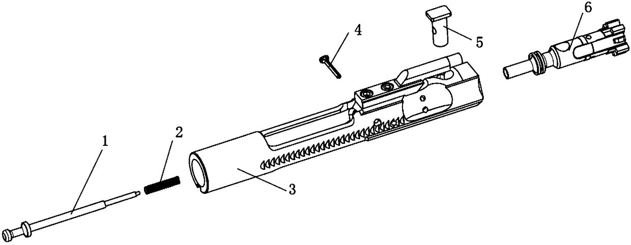
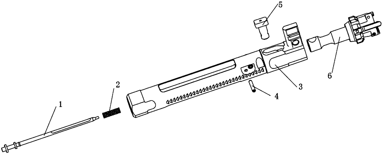
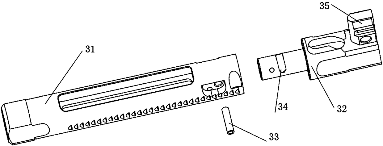
[0027] Such as figure 2 , Figure 5 As shown, an M16 bolt action structure for a shotgun includes a firing pin 1, a firing pin spring 2 sleeved on the firing pin, a machine frame assembly 3, a firing pin pin 4 connecting the firing pin and the machine frame assembly, and a guide post 5 and the machine head assembly 6, the guide post 5 is provided with a through hole for the firing pin 1 to pass through, the machine frame assembly 3 includes a guide tube 31 and a machine frame 32, and the machine frame 32 is placed on the guide tube 31 The front end is connected as a whole by the connecting pin 33 of the machine frame. The top of the machine frame 32 is provided with a spiral groove along the axial direction, and the guide post 5 is placed in the spiral groove. The inside of the machine frame 32 is p...


PUM


Abstract

The invention relates to an M16-series gunlock structure for a scattergun / shotgun. The M16-series gunlock structure comprises a striker, a striker spring, a machine frame assembly, a striker pin, a guide pillar and a machine head assembly, wherein the machine frame assembly comprises a guide pipe and a machine frame, the machine frame is arranged at the front end of the guide pipe, the machine frame and the guide pipe are connected into a whole through a machine frame connecting pin, the machine frame is provided with a spiral slot, the guide pillar is arranged in the spiral slot, and a through hole is formed in the machine frame and is communicated with the spiral slot; and the machine head assembly is arranged at the front end of the machine frame and comprises a locking body and a machine head body, the machine head body is arranged at the front end of the locking body, the locking body rotates relative to the machine head body, is connected with the machine head body through a connecting pin and is connected with the machine frame through the guide pillar, and the striker sequentially penetrates through central holes of the machine frame assembly, the guide pillar and the machine head assembly and is connected with the machine frame assembly, the guide pillar and the machine head assembly into a whole through the striker pin. By utilizing a separated machine head assembly, the locking body in the machine head assembly rotates, and the machine head body in the machine head assembly does not rotate, so that the strength of a gun barrel is not influenced by an extractor hook, the containing area of the gun barrel for cartridge cases is large, the deformation of the cartridge cases during the firing is little, and the firing safety is high.

Description

technical field [0001] The invention relates to the technical field of firearms, in particular to an M16 bolt action structure for a shotgun. Background technique [0002] The bolt action of M16 series firearms is made up of firing pin 1, firing pin spring 2, machine frame assembly 3, firing pin pin 4, guide post 5, machine head assembly 6 (see figure 1 ), when the bolt is working, the machine frame drives the machine head to rotate through the guide post to complete the opening and closing action. Because the shell hook is installed on the machine head assembly 6, when the gun bolt is locked, it needs to turn a certain angle to complete the lock, causing the barrel tail end bullet chamber to be slotted to give way to the shell hook or the bullet holding part, thereby reducing the The containment area of ​​the bullet chamber to the shell case is defined. If the shotgun / shotgun adopts this structure to fire some bullets, such as No. 12 shotgun bullets (using plastic shells ...

Claims


Application Information

Patent Timeline
Patent Type & Authority Patents(China)
IPC IPC(8): F41A19/13F41A19/30F41A19/26
CPCF41A19/13F41A19/26F41A19/30
Inventor 胡永勇黄宜民赵宏发唐成刚龚会
Owner CHONGQING JIANSHE IND GRP
Learn More