
A sinter vertical cooling furnace device and cooling method

A technology for sintering ore and cooling furnace, which is applied to furnace monitoring devices, furnace control devices, furnaces, etc., can solve the problem that the heat of the exhaust gas of the cooling machine cannot be recycled, the air temperature of the air outlet of the cooling furnace is unstable, and the temperature of the cooling air of the induced draft fan cannot be Adjustment and other issues to achieve the effect of stable air temperature, full utilization and improved stability

Active Publication Date: 2019-04-09
NORTH CHINA UNIV OF WATER RESOURCES & ELECTRIC POWER +1
View PDF3 Cites 0 Cited by
  • Summary
  • Abstract
  • Description
  • Claims
  • Application Information

AI Technical Summary

Problems solved by technology

[0003] The object of the present invention is to provide a sinter vertical cooling furnace device and cooling method, in order to solve the problem that the temperature of the cooling air provided by the induced draft fan in the traditional belt cooler or ring cooler cannot be adjusted, and also solve the problem of In the traditional technology, when adjusting the air volume of the induced draft fan, the staff needs to manually adjust it according to experience, which will easily lead to unstable air temperature at the air outlet of the cooling furnace, and the heat in the exhaust gas of the cooling machine cannot be recycled, resulting in waste of resources.

Method used


Image

  • A sinter vertical cooling furnace device and cooling method
  • A sinter vertical cooling furnace device and cooling method
  • A sinter vertical cooling furnace device and cooling method

Examples


Embodiment Construction

[0028] The technical solutions of the present invention will be clearly and completely described below in conjunction with the accompanying drawings. Apparently, the described embodiments are some of the embodiments of the present invention, but not all of them. Based on the embodiments of the present invention, all other embodiments obtained by persons of ordinary skill in the art without making creative efforts belong to the protection scope of the present invention.

[0029] In the description of the present invention, it should be noted that the terms "upper", "lower", "left", "right", "vertical", "horizontal", "inner", "outer" etc. The positional relationship is based on the orientation or positional relationship shown in the drawings, which is only for the convenience of describing the present invention and simplifying the description, rather than indicating or implying that the referred device or element must have a specific orientation, be constructed and operated in a ...


PUM


Abstract

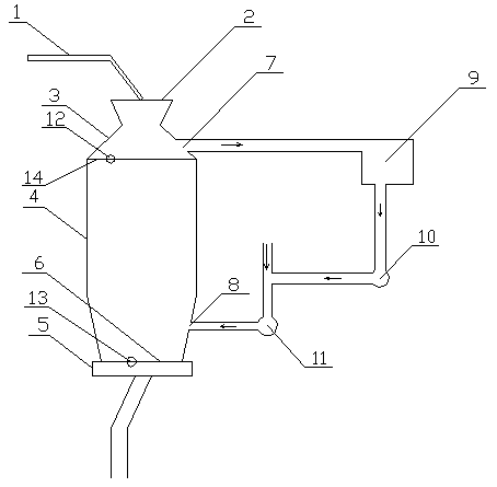
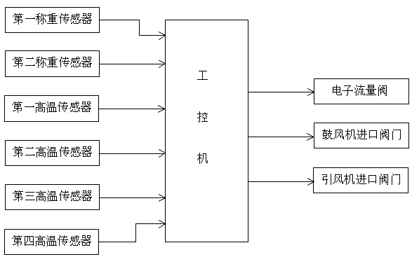
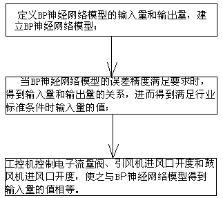
The invention provides a sinter vertical cooling furnace device and a sinter cooling method. The sinter vertical cooling furnace device comprises a belt conveying unit, a cooling furnace, a blower, an induced draft fan, a waste heat boiler and a control unit, wherein the belt conveying unit is used for inputting sinter required to be cooled down into the cooling furnace; a vibrating quantitative feeder communicates with the discharge opening of the cooling furnace, and the air outlet of the cooling furnace communicates with the air inlet of the waste heat boiler; the air inlet of the blower communicates with air, and the air outlet of the blower communicates with the air inlet of the cooling furnace; and the air outlet of the induced draft fan communicates with the air inlet of the blower, and the air inlet of the induced draft fan communicates with the air outlet of the waste heat boiler. The modeling method of a BP neural network model is utilized, and the weight value of sinter in a cooling area, the opening degree value of the air inlet of the induced draft fan and the opening degree value of the air inlet of the blower are adjusted according to the relationship between the input quantity and the output quantity, so that the temperature of the cooled sinter meets the industrial standards, the temperature stability of the air outlet of the cooling furnace is improved, and heat in waste gas of a cooler is fully utilized.

Description

technical field [0001] The invention relates to the technical field of waste heat utilization in the metallurgical industry, in particular to a sinter vertical cooling furnace device and a cooling method. Background technique [0002] The iron and steel industry is an important basic industry of the national economy, and its energy consumption accounts for about 15% of the total industrial energy consumption in the country. It is a key industry for energy conservation and emission reduction; 10-15% of the total energy consumption; at present, the sintered ore is cooled by the air medium through the belt cooler or the ring cooler. Between 100°C and 400°C, in the total energy consumption of the sintering process, nearly 50% of the heat energy is discharged in the form of sintering machine flue gas and cooling machine exhaust gas, resulting in a huge waste of energy; and industry standards stipulate: The temperature of the sintered ore at the feed port is 90°C-200°C, and the a...

Claims


Application Information

Patent Timeline
Patent Type & Authority Patents(China)
IPC IPC(8): F27D9/00F27D17/00F27D19/00F27D21/00
CPCF27D9/00F27D17/004F27D19/00F27D21/0014F27D21/0035F27D2009/0075F27D2017/006F27D2019/0003
Inventor 陈建明王为术彭岩杨旭王成凤赵明明郭香静白磊陈嘉琦彭辉白利芳
Owner NORTH CHINA UNIV OF WATER RESOURCES & ELECTRIC POWER
Learn More