
Thread transmission type electronic expansion valve

An electronic expansion valve, transmission type technology, applied in the direction of valve lift, valve details, valve device, etc., can solve the problems of high noise, complicated valve body manufacturing process, easy wear or jamming of magnetic steel sleeve, etc., to reduce friction and Effects of collision noise, simple structure, and easy manufacture

Inactive Publication Date: 2017-05-31
新昌县儒岙镇锦云机械厂
View PDF0 Cites 8 Cited by
  • Summary
  • Abstract
  • Description
  • Claims
  • Application Information

AI Technical Summary

Problems solved by technology

[0003] The purpose of the present invention is to solve the problems of high noise during operation of the existing electronic expansion valve, the magnetic steel sleeve is easy to wear or get stuck, and the valve body manufacturing process is complicated, and to provide a low noise during operation, and the magnetic steel sleeve will not wear out. or stuck, making a simple screw drive electronic expansion valve

Method used


Image

  • Thread transmission type electronic expansion valve

Examples


Embodiment Construction

[0015] Specific embodiments of the present invention will be described in detail below in conjunction with the accompanying drawings.

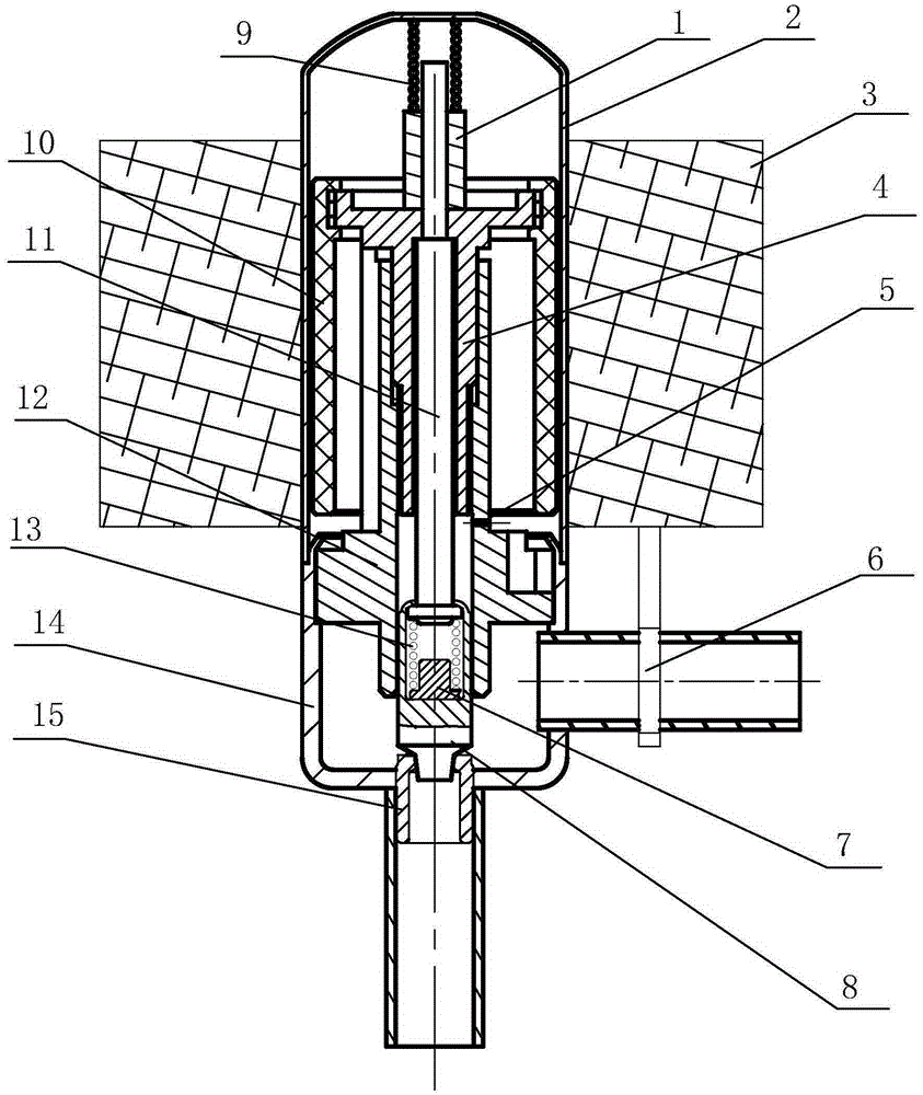
[0016] Such as figure 1 As shown, the present invention includes a valve body, a coil 3 and two medium conveying pipes. The valve body includes a housing and a valve stem part accommodated in the inner chamber of the housing, a nut sleeve 12 and a valve stem driving mechanism. The valve stem driving mechanism includes a magnetic The steel sleeve 10 and the valve stem sleeve 4, the valve stem sleeve 4 is provided with an integrally formed connection plate, the valve stem sleeve 4 is located in the inner cavity of the magnetic steel sleeve and is connected and fixed with the magnetic steel sleeve 10 through the connection plate, the outer shell is composed of an inner The front seat cover 14 with one end open and the rear seat cover 2 are docked, and the outer surface of the front seat cover is provided with a rear-facing step end face shoulder...


PUM


Abstract

The invention relates to a thread transmission type electronic expansion valve, and belongs to valves. An existing electronic expansion valve is large in running noise, and abrasion or clamping of a magnetic steel sleeve is prone to occurrence; the thread transmission type electronic expansion valve is characterized in that a backward step end face leaning shoulder is arranged on the outer circle face of a front base sleeve, the opening end of a back base sleeve is in butt joint with the step end face leaning shoulder in a fixedly welding manner to form a straight-cylinder-shaped shell with two ends closed, a front section of a nut sleeve is inserted into an inner cavity wall of the front base sleeve, and an end face leaning shoulder on the inner cavity wall and an inward turning edge of the opening end of the front base sleeve are used for limiting and fixing; a valve is installed in a hollow inner cavity of a valve rod sleeve fixed to the magnetic steel sleeve in a penetrating manner, the back end of the valve extends out of the back end of the magnetic steel sleeve, and a spacer bush and a spring arranged outside the valve rod in a sleeving manner are used for back stroke limiting; and the valve rod sleeve is matched with inner threads in an axial through hole of the nut sleeve through outer threads to drive the valve rod to move, a buffer connecting piece connected with the front end of the valve rod is arranged on the front section of the axial through hole of the nut sleeve to conduct guide supporting on the valve rod, circumferential limiting protrusions and limiting leaning shoulders which are matched with each other are arranged for front stroke limiting, and the collision noise and friction are reduced.

Description

technical field [0001] The invention belongs to the field of valves, and in particular relates to a screw drive electronic expansion valve. Background technique [0002] The electronic expansion valve is a throttling valve used to control the flow of refrigerant medium in the refrigeration system. The traditional electronic expansion valve includes a valve body, a coil mechanism, an output pipe connected to the valve hole, and an input pipe connected to the side wall of the valve cavity. , the valve hole is arranged at the front end of the front seat cover, and the valve hole is blocked or opened by an axially moving valve stem. The valve stem of the existing electronic expansion valve is a long rod, and the maximum stroke of the valve stem is limited by the guide and limit mechanism that is paired in the circumferential direction. It is easy to shake when moving, and the magnetic steel fixed to the valve stem is easy to follow. Shaking, touching the shell will cause wear ...

Claims


Application Information

Patent Timeline
IPC IPC(8): F25B41/06F16K1/00F16K31/50F16K31/06F16K1/38F16K1/42F25B41/34
CPCF16K1/00F16K1/385F16K1/42F16K31/0655F16K31/50F25B41/34F25B41/31Y02B30/70
Inventor 张锦
Owner 新昌县儒岙镇锦云机械厂
Learn More