
Solar PVT thermoelectricity co-supplying system driven by refrigerant pump

A technology of combined heat and power supply and refrigerant pump, which is applied to machines, refrigerators, refrigeration and liquefaction using solar energy, etc., can solve the problems affecting the normal operation of the system, application restrictions, freezing of cooling water, etc., to improve the comprehensive utilization efficiency, The effect of flexible switching and improving power generation efficiency

Inactive Publication Date: 2017-05-31
DALIAN UNIV OF TECH
View PDF6 Cites 9 Cited by
  • Summary
  • Abstract
  • Description
  • Claims
  • Application Information

AI Technical Summary

Problems solved by technology

In the traditional solar combined heat and power system, the cooling water will freeze when the outside temperature is low, which will affect the normal operation of the system and even damage the structure of the core of the combined heat and power module, and its application in cold regions is limited

Method used


Image

  • Solar PVT thermoelectricity co-supplying system driven by refrigerant pump
  • Solar PVT thermoelectricity co-supplying system driven by refrigerant pump
  • Solar PVT thermoelectricity co-supplying system driven by refrigerant pump

Examples


Embodiment Construction

[0023] The specific implementation manners of the present invention will be further described below in conjunction with the accompanying drawings and technical solutions.

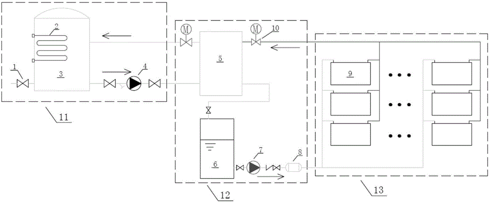
[0024] A solar PVT combined heat and power system driven by a refrigerant pump, including a power system and a refrigerant mechanical cycle solar heat pump system, and the two systems are relatively independent;

[0025] Refrigerant mechanical cycle solar heat pump system includes water subsystem and refrigerant subsystem;

[0026] The water subsystem is driven by the circulating water pump, including the heat storage tank, the circulating water pump and the plate heat exchanger; the heat exchange is realized in the plate heat exchanger, and the heat absorbed by the refrigerant is transferred to the water, and the circulating water pump is used as the power device , store the heat of hot water in the heat storage tank, thus completing the water system cycle.

[0027] The refrigerant subsystem is powered by...


PUM


Abstract

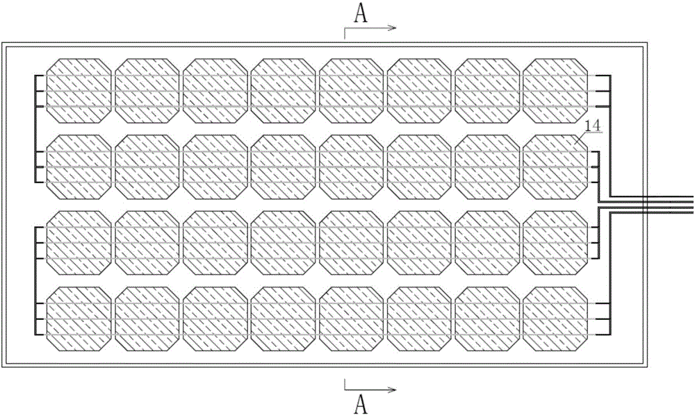
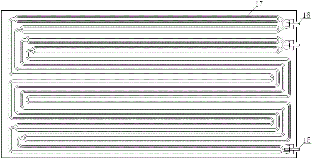
The invention discloses a solar PVT thermoelectricity co-supplying system driven by a refrigerant pump. The solar PVT thermoelectricity co-supplying system driven by the refrigerant pump comprises an electrical power system and a refrigerant mechanical circulation solar heat pump system, and the electrical power system and the refrigerant mechanical circulation solar heat pump system are relativelyindependent; the refrigerant mechanical circulation solar heat pump system comprises a water subsystem and a refrigerant subsystem; a circulating water pump is adopted as power drive for the water subsystem, and the water subsystem comprises a heat storage water tank, the circulating water pump and a plate type heat exchanger. The refrigerant subsystem is driven by a refrigerant pump, and comprises an efficient solar thermoelectricity co-generation component, a plate type heat exchanger, the refrigerant pump, and a liquid storage tank, the refrigerant pump sends liquid refrigerant in the liquid storage tank into a heat exchanging tube flow channel of the efficient solar thermoelectricity co-generation component, refrigerant vapor in the heat exchanging tube flow channel enters the plate type heat exchanger, and conducts heat exchanging with water in the plate type heat exchanger, when the refrigerant vapor is condensed into liquid, heat is released at the same time, and then the condensate refrigerant is converged into the liquid storage tank. The electrical power system is designed into a grid combining power generation system, a mains supply complementary off-grid power generation system and an energy storage and microgrid system, and the grid combining power generation system, the mains supply complementary off-grid power generation system and the energy storage and microgrid system are synergetically and cooperatively used and flexibly transformed and switched.

Description

technical field [0001] The invention relates to a novel refrigerant mechanical circulation solar heat pump system driven by a refrigerant pump, which can synchronously and efficiently develop and utilize solar energy resources and a solar PVT combined heat and power system. Background technique [0002] Solar collectors have been widely used in energy power, refrigeration and air conditioning, social life, aerospace technology and other fields, but there are many problems in the utilization of solar energy. The low utilization rate of solar energy is the bottleneck of solar energy utilization at present. The solar cogeneration system, which can significantly improve the comprehensive utilization efficiency of solar energy in the process of solar photovoltaic power generation, solve the cooling problem of photovoltaic cells, and realize the simultaneous and deep development and utilization of solar photovoltaic / photothermal resources, has begun to show its performance advanta...

Claims


Application Information

Patent Timeline
IPC IPC(8): F25B27/00H02S40/44H02S40/42
CPCH02S40/425H02S40/44F25B27/002Y02E10/60Y02E10/50
Inventor 张吉礼周超梁若冰路世翔
Owner DALIAN UNIV OF TECH
Learn More