


Quick Research
Generate reliable direction feasibility study reports for your R&D in just a few steps.

Technical Q&A
Discover and master advanced knowledge NOW. Basics, ideas, possibilities, all at once.

Find Solutions
As an expert in R&D theories, this can generate solutions to your technical problems instantly.

Evaluate Feasibility
Analyze your overall solution with one click, know your potential R&D risks in advance.

Monitor Landscape
Get weekly tech updates, stay abreast of the latest tech innovations and key insights.
Electronic cigarette light-up circuit and ashtray based on electronic cigarette light-up circuit
An electronic cigarette lighting and ashtray technology, applied in the electronic field, can solve problems such as poor experience, safety, poor functionality and intelligence, and achieve the effects of good intelligence, improved safety, and low static current
- Summary
- Abstract
- Description
- Claims
- Application Information
AI Technical Summary
Problems solved by technology
Method used
Image

Examples
Embodiment 1
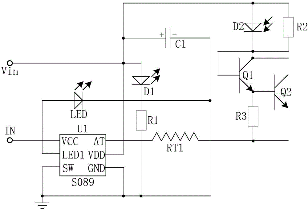
[0029] Such as figure 1 As shown, an electronic cigarette lighting circuit is mainly composed of a control chip U1, a triode Q1, a triode Q2, a signal light LED connected to the P pole of the LED1 pin of the control chip U1, and connected to the GND pin of the control chip U1. , the P pole is connected to the VDD pin of the control chip U1, the N pole is connected to the GND pin of the control chip U1 after the resistor R1, the positive pole is connected to the P pole of the light emitting diode D1, and the negative pole is connected to the signal lamp LED Capacitor C1 connected to the N pole of the capacitor C1, one end connected to the AT pin of the control chip U1, the other end connected to the emitter of the triode Q2 heating wire RT1, the P pole connected to the positive pole of the capacitor C1, and the N pole connected to the triode A photodiode D2 connected to the collector of Q1, a resistor R2 connected in parallel with the photodiode D2, and a resistor R3 connected ...
Embodiment 2
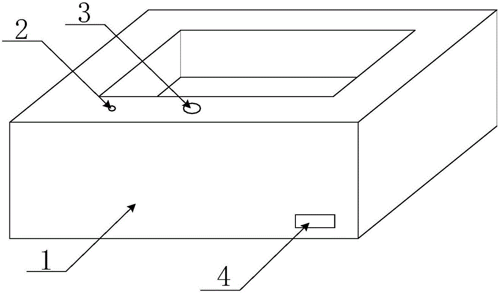
[0035] Such as figure 2 , 3 As shown, the ashtray based on the electronic cigarette lighting circuit includes the main body of the ashtray and the electronic cigarette lighting circuit arranged inside the main body of the ashtray. The main body of the ashtray is also provided with an indicator position 2, a smoke inlet hole 3 and a USB interface. bit 4.
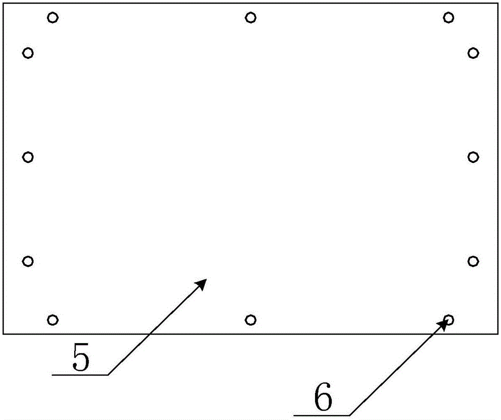
[0036] The main body of the ashtray is composed of an ashtray upper shell 1 and an ashtray bottom plate 5, and the ashtray upper shell 1 and the ashtray bottom plate 5 are solidly integrated. The upper shell 1 of the ashtray can be designed in different shapes according to actual needs, not only can be designed as ordinary geometric shapes, but also can be designed as various shapes with more aesthetic feeling.
[0037] The ashtray bottom plate 5 is provided with a fixing hole 6, and the ashtray bottom plate 5 and the ashtray upper shell 1 are fixed together by screws. The bottom plate of the ashtray and the upper shell o...
PUM
 Abstract
Description
Claims
Application Information
 - R&D Engineer
- R&D Manager
- IP Professional
- Industry Leading Data Capabilities
- Powerful AI technology
- Patent DNA Extraction
Browse by: Latest US Patents, China's latest patents, Technical Efficacy Thesaurus, Application Domain, Technology Topic, Popular Technical Reports.
© 2024 PatSnap. All rights reserved.Legal|Privacy policy|Modern Slavery Act Transparency Statement|Sitemap|About US| Contact US: help@patsnap.com