
Rubber sealing ring

A technology of rubber sealing ring and outer sealing ring, applied in the direction of engine sealing, mechanical equipment, engine components, etc., can solve the problems of poor oil resistance of the sealing ring, inconvenient installation and maintenance, single function of the sealing ring, etc. High performance, convenient one-time molding, and the effect of reducing equipment cost

Inactive Publication Date: 2017-05-31
东莞市瑞拓五金橡塑有限公司
View PDF9 Cites 2 Cited by
  • Summary
  • Abstract
  • Description
  • Claims
  • Application Information

AI Technical Summary

Problems solved by technology

[0002] The rubber sealing ring is an annular cover composed of one or several parts, which is fixed on a ring or washer of the bearing and contacts with another ring or washer or forms a narrow labyrinth gap to prevent the leakage of lubricating oil and the intrusion of foreign objects. Rubber sealing rings can be divided into O-shaped sealing rings, Y-shaped sealing rings and V-shaped sealing rings according to their cross-sectional shapes. However, the above-mentioned various sealing rings can only achieve a single function, such as oil seal or air seal. The sealing of the rotating shaft in the occasion needs to apply radial force to the rotating shaft to prevent the leakage of fluid or lubricating oil, and also to prevent the intrusion of dust or sand from the outside. In order to achieve the above functions, the end of the existing rotating shaft is equipped with two The seal ring is used to realize the functions of oil seal and air seal respectively, which is inconvenient to install and maintain, and the existing seal ring has poor oil resistance and short service life

Method used


Image

  • Rubber sealing ring

Examples


Embodiment Construction

[0009] The technical solutions in the embodiments of the present invention are clearly and completely described below in conjunction with the accompanying drawings in the embodiments of the present invention. Obviously, the described embodiments are only part of the embodiments of the present invention, not all of them. Based on the embodiments of the present invention, all other embodiments obtained by persons of ordinary skill in the art without making creative efforts belong to the protection scope of the present invention.


PUM


Abstract

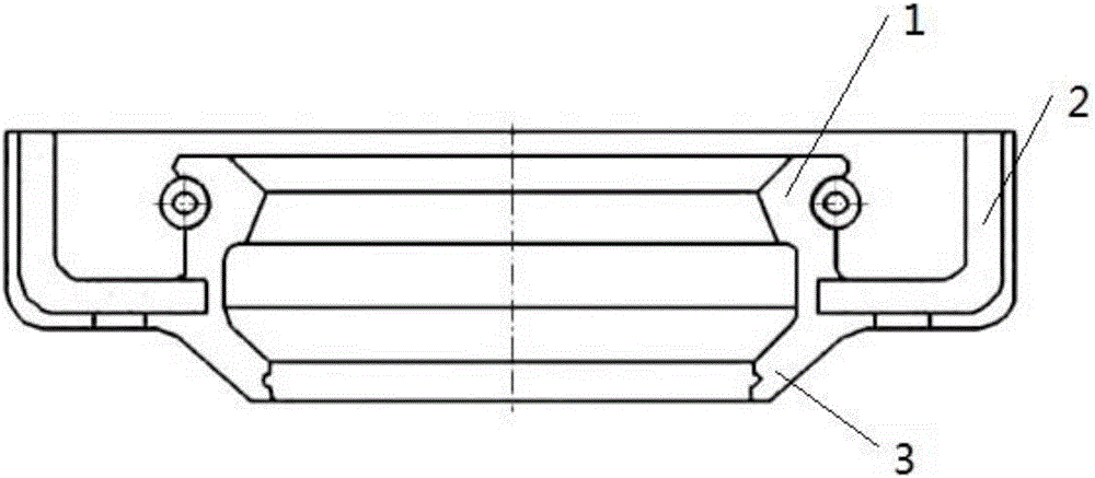
The invention discloses a rubber sealing ring. The rubber sealing ring comprises an annular skeleton 2, a silica layer, an inner sealing ring 1 and an outer sealing ring 3, wherein the section shape of the annular skeleton 2 is L-shaped; the outer side of the annular skeleton 2 is coated with the silica layer; the inner sealing ring 1 and the outer sealing ring 3 are arranged on the inner side of the annular skeleton 2; the silica layer, the inner sealing ring and the outer sealing ring are integrally formed; the silica layer, the inner sealing ring and the outer sealing ring are formed by mixing the following raw materials in parts by weight: 100 parts of raw rubber, 20 to 25 parts of an active agent, 5 parts of a plasticizer, 3 parts of an anti-ageing agent, 10 parts of a reinforcing agent, 10 parts of a plasticizer, 5 parts of an accelerant and 1 part of a vulcanizing agent; the inner sealing ring and the outer sealing ring are arranged on the inner side and the outer side of the L-shaped skeleton correspondingly; the inner sealing ring realizes oil seal and the outer sealing ring realizes gas seal; meanwhile, the inner sealing ring and the outer sealing ring adopt rubber materials with high oil resistance, have high surface polarity and high stability, are insusceptible to swelling, and meet the requirements of oil seal and gas seal.

Description

technical field [0001] The invention relates to the technical field of sealing rings, in particular to a rubber sealing ring. Background technique [0002] The rubber sealing ring is an annular cover composed of one or several parts, which is fixed on a ring or washer of the bearing and contacts with another ring or washer or forms a narrow labyrinth gap to prevent the leakage of lubricating oil and the intrusion of foreign objects. Rubber sealing rings can be divided into O-shaped sealing rings, Y-shaped sealing rings and V-shaped sealing rings according to their cross-sectional shapes. However, the above-mentioned various sealing rings can only achieve a single function, such as oil seal or air seal. The sealing of the rotating shaft in the occasion needs to apply radial force to the rotating shaft to prevent the leakage of fluid or lubricating oil, and also to prevent the intrusion of dust or sand from the outside. In order to achieve the above functions, the end of the e...

Claims


Application Information

Patent Timeline
Patent Type & Authority Applications(China)
IPC IPC(8): F16J15/3248C08L9/02C08K13/02C08K3/22C08K5/11C08K5/18C08K3/26C08K5/12C08K5/40C08K5/47
CPCF16J15/3248C08K3/22C08K3/26C08K5/11C08K5/12C08K5/18C08K5/40C08K5/47C08K13/02C08K2003/2296C08K2003/265C08K2201/011C08L9/02
Inventor 徐应斌
Owner 东莞市瑞拓五金橡塑有限公司
Learn More