A clutch cylinder thrust conversion mechanism

A technology of clutch wheel pump and conversion mechanism, which is applied in the direction of clutch, mechanical equipment, etc., can solve the problem that the clutch wheel pump cannot be used.

Active Publication Date: 2019-02-19
ANHUI JIANGHUAI AUTOMOBILE GRP CORP LTD
View PDF8 Cites 0 Cited by
  • Summary
  • Abstract
  • Description
  • Claims
  • Application Information

AI Technical Summary

Problems solved by technology

[0004] The fixed structure of the clutch cylinder in the prior art is suitable for the conventional transmission structure. The fixed relative position of the clutch rocker arm and the clutch cylinder of this structure is in line with the thrust direction of the required clutch cylinder. However, in actual use, the relative position cannot be directly arranged This structure cannot be used when the pump is used to provide the thrust of the push rod

Method used


Image

  • A clutch cylinder thrust conversion mechanism
  • A clutch cylinder thrust conversion mechanism
  • A clutch cylinder thrust conversion mechanism

Examples


Embodiment Construction

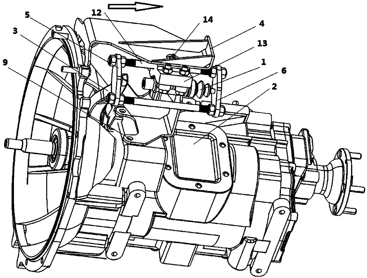
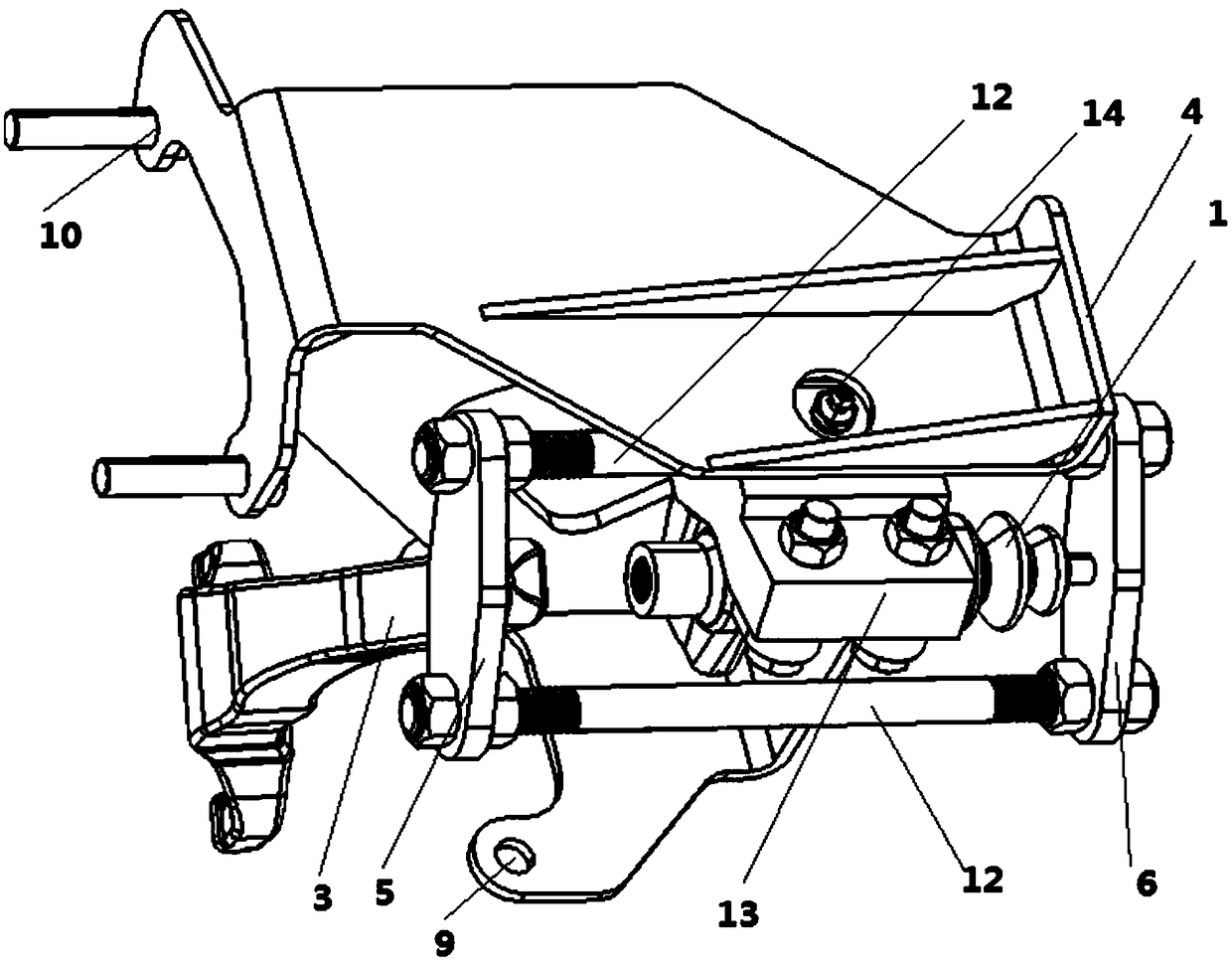
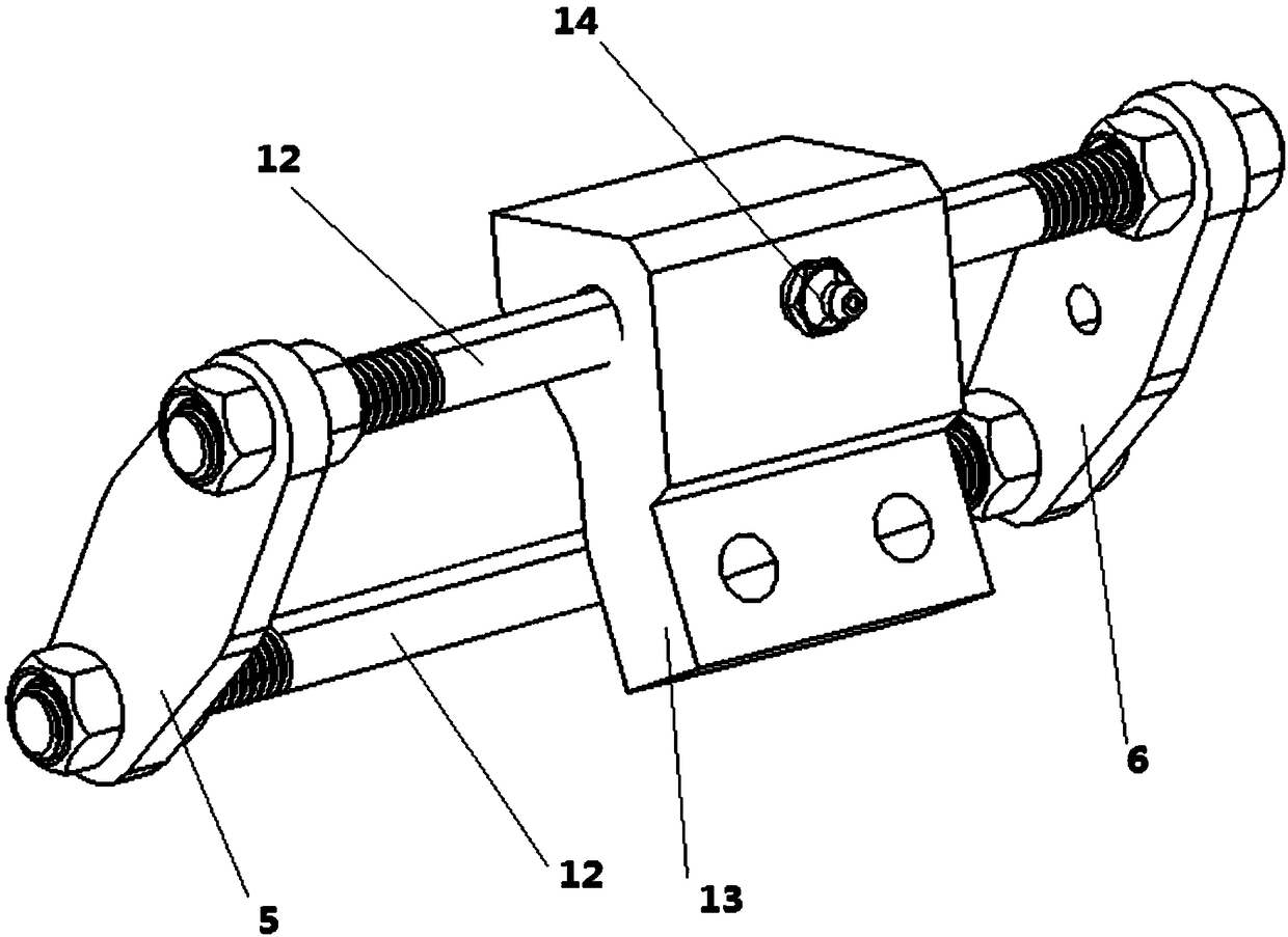
[0013] Such as Figures 1 to 4 As shown, the present invention provides a clutch wheel pump thrust conversion mechanism, which includes a clutch separation pump 1, the clutch separation pump 1 is fixedly connected to the transmission 2 and pushes the separation shift fork 3 toward the transmission 2, and it also includes: Clutch cylinder support 4, the clutch separation pump 1 is fixedly installed on the clutch separation cylinder support 4, and the clutch separation cylinder support 4 is fixedly connected with the transmission side and the steering wheel side respectively; The pump thrust conversion mechanism also includes an inner thrust plate 5 and an outer thrust plate 6, both of which are driven by the clutch separation pump 1, and the separation shift fork 3 is located in the inner thrust plate 6. between the thrust plate 5 and the outer thrust plate 6 .

[0014] The invention converts the thrust of the clutch slave cylinder into the pulling force on the separation shif...


PUM


Abstract

The invention provides a thrust conversion mechanism of a clutch slave cylinder. The clutch slave cylinder is fixedly mounted on a clutch slave cylinder bracket; the clutch slave cylinder bracket is fixedly connected with a transmission side and a steering wheel side; the thrust conversion mechanism is provided with an inner thrust plate and an outer thrust plate, which are driven by the clutch slave cylinder; a separation shifting fork is located between the inner thrust plate and the outer thrust plate; a thrust of the clutch slave cylinder is converted into a pulling force of the separation shifting fork through a design structure of a fixed bracket, the inner thrust plate and the outer thrust plate, so that installation and utilization requirements of the clutch slave cylinder are met when relative positions of the clutch slave cylinder and the separation shifting fork do not accord with the direction of the needed thrust.

Description

technical field [0001] The invention relates to a thrust conversion mechanism of a clutch cylinder. Background technique [0002] Automobile clutch separation generally applies pressure to the clutch pedal by manpower, which is converted into hydraulic pressure output by the clutch master cylinder, and then transferred to the clutch slave cylinder to be converted into push rod thrust output to the clutch fork to push the clutch to achieve separation. The conversion of the hydraulic pressure into the push rod thrust by the clutch cylinder requires a more reasonable design of the fixing bracket, and the traditional clutch cylinder fixing bracket design is generally relatively simple. [0003] The fixed structure of the traditional clutch slave cylinder, the clutch slave cylinder is installed on the transmission through a simple fixed bracket, the push rod is connected with the clutch release rocker arm, and the clutch is separated by pushing the release rocker arm in the direc...

Claims


Application Information

Patent Timeline
Patent Type & Authority Patents(China)
IPC IPC(8): F16D48/04
CPCF16D48/00F16D48/04
Inventor 陈光明武煌熊仕宇张翔赵刚
Owner ANHUI JIANGHUAI AUTOMOBILE GRP CORP LTD
Why Eureka
Try Eureka