
Construction method of concrete anti-corrosion tooling in splash zone of steel cylindrical revetment structure

A construction method and technology of steel cylinders, applied in infrastructure engineering, underwater structures, artificial islands, etc., can solve problems such as hidden safety hazards, corrosion, and impacts on the subsequent development and utilization of artificial islands, and improve safety , reduce the load, and facilitate installation

Active Publication Date: 2019-01-04
CHINA CONSTR SIXTH ENG DIV CORP
View PDF5 Cites 0 Cited by
  • Summary
  • Abstract
  • Description
  • Claims
  • Application Information

AI Technical Summary

Problems solved by technology

However, the position of the cylindrical revetment structure of the steel structure near the water surface (splash area) is easily caused by corrosion due to alternate contact with seawater and air.
The corrosion of the permanent steel revetment structure poses a great safety hazard to the operation of the entire artificial island
[0003] The measures such as heavy-duty anti-corrosion coatings and cathodic protection commonly used in the known field cannot meet the century-long long-term anti-corrosion requirements of steel structures in the splash zone in the sea. Therefore, there is currently no reliable method for effective anti-corrosion protection of steel revetment structures.
It is difficult to ensure that the permanent steel enclosure structure in the sea can achieve the designed service life, which seriously affects the subsequent development and utilization of artificial islands

Method used

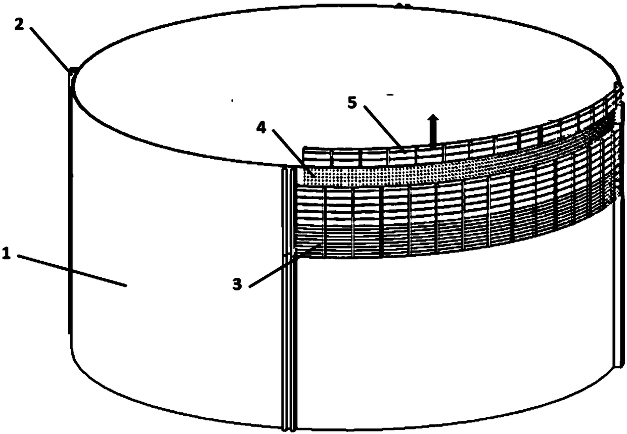
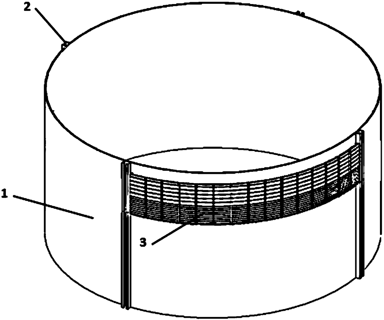
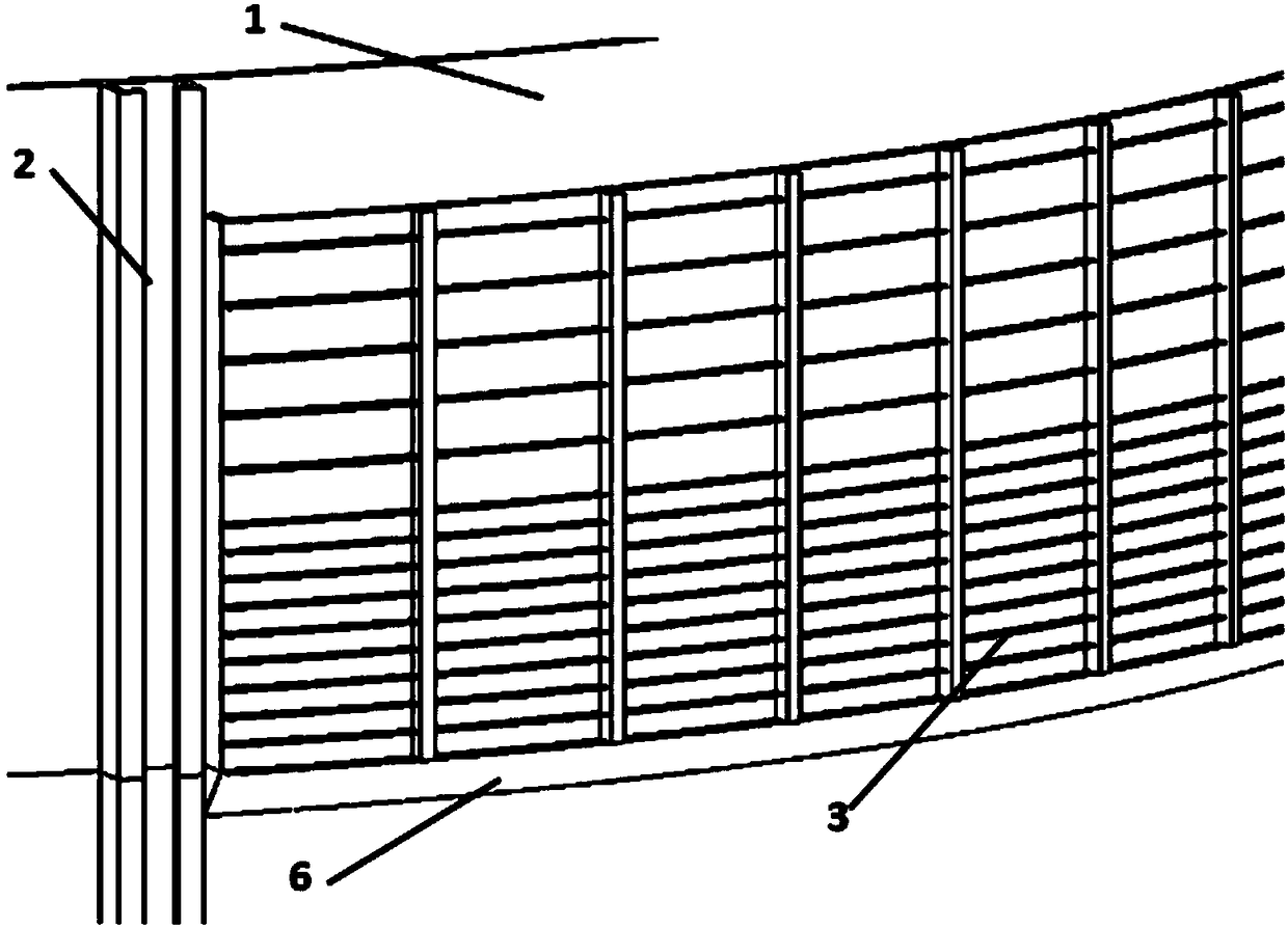

Image

  • Construction method of concrete anti-corrosion tooling in splash zone of steel cylindrical revetment structure
  • Construction method of concrete anti-corrosion tooling in splash zone of steel cylindrical revetment structure
  • Construction method of concrete anti-corrosion tooling in splash zone of steel cylindrical revetment structure

Examples


Embodiment 1

[0039] (1) Fix the shear connection structure on the outer wall of the splash area of ​​the steel cylindrical bank revetment structure with a tongue and groove structure, the distance between the top of the shear connection structure and the top of the revetment structure is 15cm, so The height of the shear connection structure described above is 4.8m;

[0040] (2) Weld the bottom mold support plate in the circumferential range of the revetment structure splash zone at the bottom of the shear connection structure at a predetermined distance;

[0041] (3) An arc-shaped fixed formwork is installed at the bottom of the shear connection structure, and a horizontally arranged arc-shaped bottom wall is welded at the bottom of the fixed formwork, and the bottom wall of the fixed formwork is connected to the outer wall of the revetment structure by welding and the fixed formwork The bottom wall and the support plate are welded and fixed, and the left and right side walls of the fixed ...

Embodiment 2

[0047] (1) Fix the shear connection structure on the outer wall of the splash area of ​​the steel cylindrical bank revetment structure with a tongue and groove structure, the distance between the top of the shear connection structure and the top of the revetment structure is 20cm, so The height of the shear connection structure described above is 5m;

[0048] (2) Weld the bottom mold support plate in the circumferential range of the revetment structure splash zone at the bottom of the shear connection structure at a predetermined distance;

[0049] (3) An arc-shaped fixed formwork is installed at the bottom of the shear connection structure, and a horizontally arranged arc-shaped bottom wall is welded at the bottom of the fixed formwork, and the bottom wall of the fixed formwork is connected to the outer wall of the revetment structure by welding and the fixed formwork The bottom wall and the support plate are welded and fixed, and the left and right side walls of the fixed fo...

Embodiment 3

[0055] (1) Fix the shear connection structure on the outer wall of the splash area of ​​the steel tubular bank revetment structure with a tongue and groove structure, the distance between the top of the shear connection structure and the top of the revetment structure is 18cm, so The height of the shear connection structure described above is 4.5m;

[0056] (2) Weld the bottom mold support plate in the circumferential range of the revetment structure splash zone at the bottom of the shear connection structure at a predetermined distance;

[0057] (3) An arc-shaped fixed formwork is installed at the bottom of the shear connection structure, and a horizontally arranged arc-shaped bottom wall is welded at the bottom of the fixed formwork, and the bottom wall of the fixed formwork is connected to the outer wall of the revetment structure by welding and the fixed formwork The bottom wall and the support plate are welded and fixed, and the left and right side walls of the fixed form...


PUM


Abstract

The invention discloses a construction method for concrete anti-corrosion tooling in the splash area of ​​a steel cylindrical bank revetment structure, which comprises the following steps: fixing a shear-resistant connection structure on the outer wall of the circumferential range of the splash area of ​​the steel cylindrical bank revetment structure with a tongue-and-groove structure; Weld the bottom formwork support plate at the circumference of the revetment structure splash area with a predetermined distance at the bottom of the shear connection structure; an arc-shaped fixed formwork is installed on the lower part of the shear-resistance connection structure, and a horizontally arranged arc-shaped bottom is welded at the bottom of the fixed formwork wall; hoist the steel cylindrical revetment structure into the water; install water-stop sealing strips on the top of the front wall of the fixed formwork and the top of the left and right side walls; pump out the water in the cavity between the fixed formwork and the movable formwork and the revetment structure, and then Covering concrete is poured in the cavity. The adoption of the method can ensure the long-term anti-corrosion of the offshore steel cylindrical revetment structure within its service life.

Description

technical field [0001] The invention relates to the field of offshore artificial island construction, in particular to a construction method for concrete anti-corrosion tooling in the splash area of ​​a steel cylindrical revetment structure. Background technique [0002] The steel cylindrical revetment structure is a new technology in the construction of offshore artificial islands. The structure has the characteristics of fast construction, factory manufacturing, and low impact on the environment. It is the key technology to realize the rapid construction of artificial islands. However, the position of the cylindrical revetment structure of the steel structure near the water surface (splash area) is very easy to cause corrosion due to alternate contact with seawater and air. The corrosion of the permanent steel revetment structure poses a great safety hazard to the operation of the entire artificial island. [0003] The measures such as heavy-duty anti-corrosion coatings ...

Claims


Application Information

Patent Timeline
Patent Type & Authority Patents(China)
IPC IPC(8): E02B17/00
CPCE02B17/00E02B17/0008E02B17/0026
Inventor 周俊龙李洋刘强叶道海张纪亮苏光林赵红阳
Owner CHINA CONSTR SIXTH ENG DIV CORP
Learn More