Entrance looper mechanism, system and method for controlling looper of continuous withdrawal line

A control method and looper technology, which is applied in the field of steel rolling, can solve the problem of drawing the lead into the annealing furnace, etc., and achieve the effect of reducing the troubleshooting time and avoiding the secondary broken belt

Active Publication Date: 2018-12-14
SHOUGANG JINGTANG IRON & STEEL CO LTD
View PDF8 Cites 0 Cited by
  • Summary
  • Abstract
  • Description
  • Claims
  • Application Information

AI Technical Summary

Problems solved by technology

[0004] The embodiment of the present invention solves the technical problem in the prior art that the strip head will be drawn into the annealing furnace after the strip steel in the entrance loop is broken by providing an entry loop mechanism, system and continuous annealing line loop control method

Method used


Image

  • Entrance looper mechanism, system and method for controlling looper of continuous withdrawal line
  • Entrance looper mechanism, system and method for controlling looper of continuous withdrawal line
  • Entrance looper mechanism, system and method for controlling looper of continuous withdrawal line

Examples


Embodiment Construction

[0027] In order to make the purpose, technical solutions and advantages of the embodiments of the present invention clearer, the technical solutions in the embodiments of the present invention will be clearly and completely described below in conjunction with the drawings in the embodiments of the present invention. Obviously, the described embodiments It is a part of embodiments of the present invention, but not all embodiments. Based on the embodiments of the present invention, all other embodiments obtained by persons of ordinary skill in the art without creative efforts fall within the protection scope of the present invention.

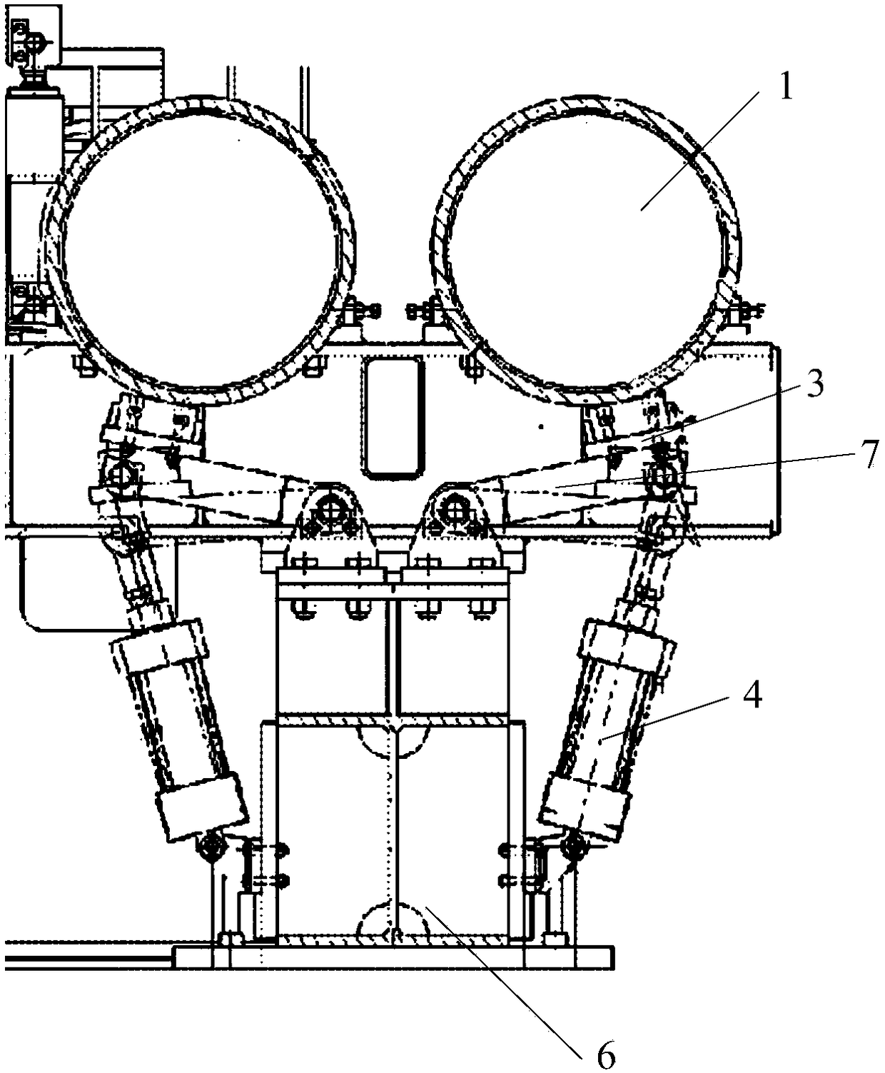
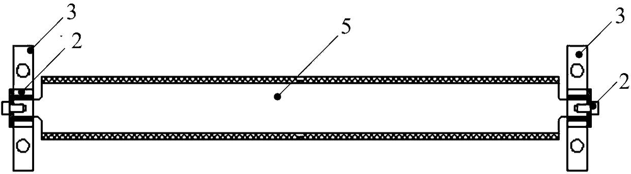
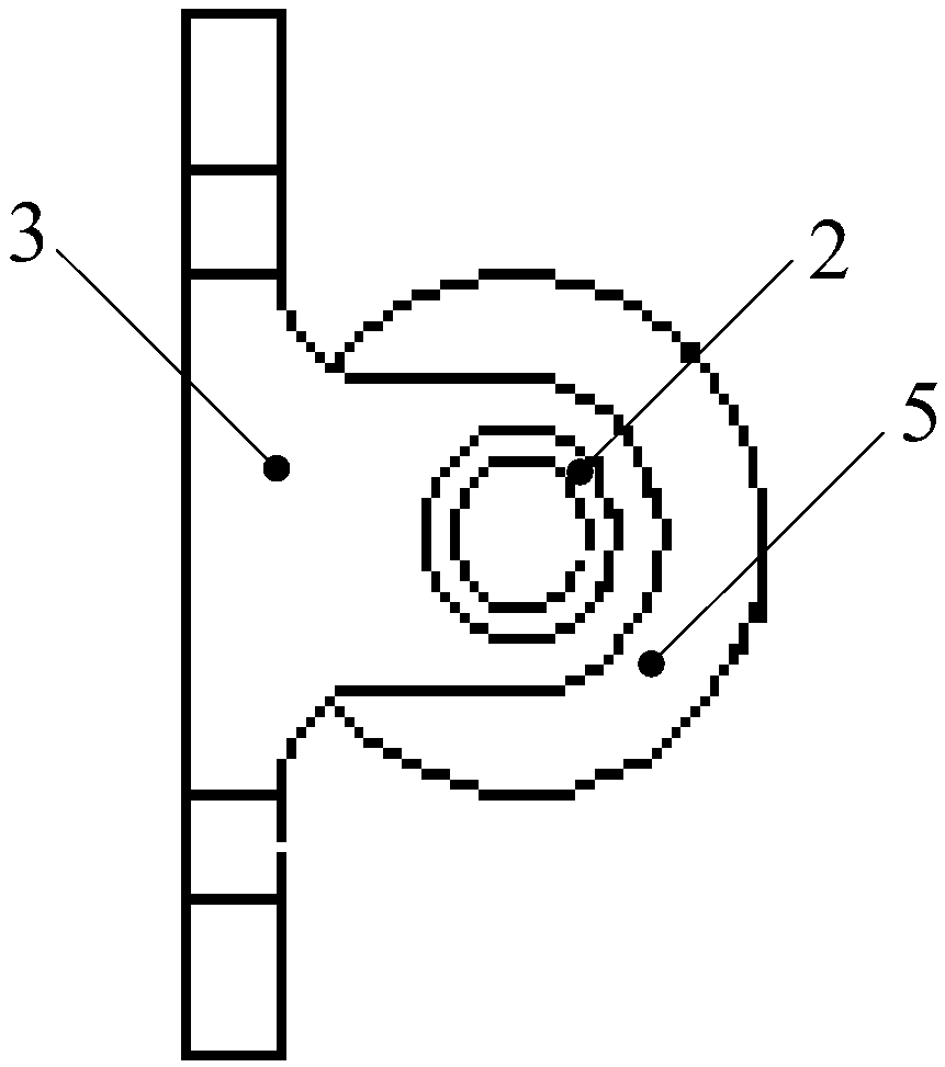
[0028] refer to Figure 1 ~ Figure 4 As shown, the present invention provides an inlet looper mechanism 10 .

[0029] The entrance looper mechanism 10 includes: a looper bottom roller 1, a bearing 2, a bearing seat 3, a pneumatic actuator 4, a brake roller 5, a base 6, and a connecting rod 7. The bearing seat 3 is set on the roll side of the loo...


PUM

PropertyMeasurementUnit
diameteraaaaaaaaaa

Abstract

The invention discloses an entry loop mechanism and system and a continuous annealing line loop control method. The entry loop mechanism and system and the continuous annealing line loop control method are applied to the technical field of steel rolling. The entry loop mechanism comprises a loop bottom roller, a bearing, a bearing seat, a pneumatic performing mechanism, a band-type brake roller, a base and a connection rod. The bearing seat is arranged in the roller side face position of the loop bottom roller. The band-type brake roller is assembled in the bearing seat through the bearing. The bearing seat is fixed to the first end of the connection rod. The second end of the connection rod is hinged to the base. A fixed part of the pneumatic performing mechanism is connected to the base. A movable part of the pneumatic performing mechanism is hinged to the second end of the connection rod. The technical problem that in the prior art, after strip steel in an entry loop is broken, a strip head is sucked in an annealing furnace is solved, and the fault handling time is shortened greatly.

Description

technical field [0001] The invention relates to the technical field of steel rolling, in particular to an inlet looper mechanism, a system and a method for controlling the looper of a continuous withdrawal line. Background technique [0002] The continuous annealing unit is an important link in the production of cold-rolled strip steel. It has a series of advantages such as short process, high output, and good product quality. It is an indispensable annealing equipment. The entrance speed of the high-speed continuous annealing line is fast. When producing thin-gauge strip steel, belt breakage often occurs in the cleaning section and the entrance looper. For example, the 1420 continuous withdrawal line has a maximum design speed of 1000m / min at the entrance, a maximum speed of 750m / min in the furnace area, and a maximum speed of 1100m / min at the exit. Belt breaks often occur in the cleaning section and the inlet looper during production. [0003] Currently, the brake block ...

Claims


Application Information

Patent Timeline
Patent Type & Authority Patents(China)
IPC IPC(8): C21D9/56C21D11/00C21D1/26
CPCC21D1/26C21D9/562C21D9/564
Inventor 杨世勇任伟超王连庆郑晓飞刘宗发刘冰扬史云峰王晓广周玉峰
Owner SHOUGANG JINGTANG IRON & STEEL CO LTD
Why Eureka
Try Eureka