
Rotary blowing equipment and method for molten iron desulphurization

A technology of rotary injection and molten iron desulfurization, applied in the field of iron and steel smelting molten iron pretreatment, can solve the problems of high consumption of desulfurization agent, low desulfurization efficiency, complex metallurgical equipment, etc., to improve production safety, good equipment power conditions, and desulfurization powder Low consumption effect

Active Publication Date: 2017-05-31
鞍山市和丰耐火材料有限公司
View PDF17 Cites 3 Cited by
  • Summary
  • Abstract
  • Description
  • Claims
  • Application Information

AI Technical Summary

Problems solved by technology

Disadvantages of the injection method: the desulfurization powder and the sulfur in the molten iron 18 cannot be fully combined, the desulfurization efficiency is low, and the consumption of desulfurization agent is high
Inadequacies of the KR method: the metallurgical equipment used is complicated and the cost is high
[0007] However, the power unit of the device uses four motors to clamp the drive from the side of the spray gun, and the space it occupies is still very large
The two transmission motors installed from the side make the spray gun rotate left and right alternately. This rotation mode makes the blade of the spray gun always move against the rotation direction of the molten iron. Second, the stirring of molten iron is not uniform, the mixing effect of desulfurization powder and molten iron is not good, and the desulfurization effect is not good; the third is that it is more likely to cause shaking of equipment
In addition, the use of two motors only clamps and fixes the rotary spray gun body alone, which cannot guarantee the stability and non-shaking of the entire device

Method used


Image

  • Rotary blowing equipment and method for molten iron desulphurization
  • Rotary blowing equipment and method for molten iron desulphurization
  • Rotary blowing equipment and method for molten iron desulphurization

Examples


Embodiment 1

[0046] The desulfurization production line of a steel factory in Northeast China was built in 1999, which belongs to the injection method desulfurization. In recent years, with the increase of the proportion of high-quality steel, the requirements for deep desulfurization of molten iron have been increasing day by day. The original spray desulfurization method can no longer meet the new smelting conditions and requirements. Therefore, after 2010, the desulfurization production lines in the new work area of ​​the steel plant all adopt the KR method. , but the transformation of the original injection method production line is very difficult, the biggest problem is the small space, and the transformation changes greatly and the investment is also large, so it cannot be implemented.

[0047] Later, the molten iron desulfurization spinning rotor method (spinning rotor) of the present invention, hereinafter referred to as the SR method, was adopted. With only a little reinforcement ...


PUM


Abstract

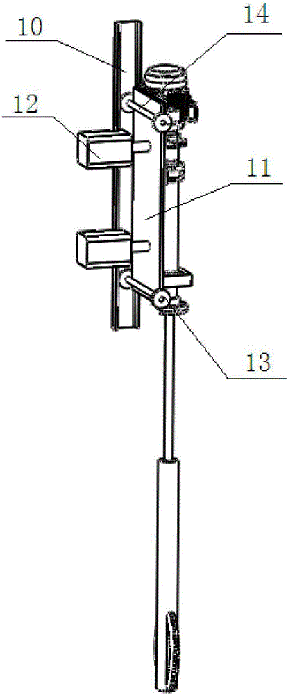
Provided are rotary blowing equipment and method for molten iron desulphurization. The rotary blowing equipment comprises a rotating mechanism, a traveling trolley, a U-steel track and a positioning air cylinder, wherein the U-steel track is longitudinally fixed to a metal steel structure framework, the traveling trolley travels in the U-steel track through traveling wheels, a bearing block of the rotating mechanism and a motor are fixed to the traveling trolley, the air cylinder is arranged on the back side of the traveling trolley, one end of the air cylinder is fixed to the metal steel structure framework, and the other end of the air cylinder is connected with the traveling trolley in an abutting mode. Compared with the prior art, the rotary blowing equipment and method for molten iron desulphurization have the beneficial effects that the degree of integration is higher, and the occupied space is small; the power condition is good, and the equipment is stable in use and free of shaking; molten iron is stirred evenly, desulfuration is conducted efficiently, the production efficiency is high, consumption of desulphurization powder is low, and the production cost is reduced; and the technical conditions of smelting of pure steel can be met.

Description

technical field [0001] The invention relates to the technical field of pretreatment of molten iron in iron and steel smelting, in particular to a rotary injection device and an injection method for desulfurization of molten iron. Background technique [0002] Hot metal desulfurization is a hot metal treatment technology that was researched and applied in the 1950s and 1960s. At present, there are two methods of hot metal desulfurization widely used in domestic steel mills: injection method and KR method. [0003] See Figure 8 The injection method is to use inert gas as a carrier to spray the desulfurization powder into the molten iron 18 through the spray gun 20 made of refractory material, so that the desulfurization agent and the molten iron 18 react, so as to achieve the purpose of desulfurization. Disadvantages of the injection method: the desulfurization powder and the sulfur in the molten iron 18 cannot be fully combined, the desulfurization efficiency is low, and th...

Claims


Application Information

Patent Timeline
IPC IPC(8): C21C7/064C21C1/02
Inventor 李涛孙逊廉占禄单鹏继
Owner 鞍山市和丰耐火材料有限公司
Learn More