
Compost fermentation tank

A fermentation tank and composting technology, applied in the field of composting fermentation tanks, can solve the problems of inaccurate measurement data, inability to achieve real-time measurement, and poor representativeness of detected gas, so as to avoid clogging of pores, facilitate transportation and transfer, and have small concentration changes Effect

Inactive Publication Date: 2017-05-31
BEIJING ACADEMY OF AGRICULTURE & FORESTRY SCIENCES
View PDF7 Cites 7 Cited by
  • Summary
  • Abstract
  • Description
  • Claims
  • Application Information

AI Technical Summary

Problems solved by technology

Online real-time measurement has the advantage of collecting data in a timely manner, but it has relatively high requirements for the surrounding environment of the collection site. Once the surrounding environment such as temperature and humidity, air flow rate, etc. change, the accuracy and sensitivity of the collected data will be greatly affected, resulting in The measurement data is inaccurate; gas collection--laboratory detection is less affected by the environment because the detection process is in the laboratory, and the detection data is accurate. However, due to manual timing collection, the representativeness of the detection gas is poor and cannot be done. to real-time measurement
The above two measurement methods have their own advantages and disadvantages. How to learn from each other and achieve accurate real-time gas detection that is less affected by the surrounding environment is a difficult point in the current compost fermentation gas detection.

Method used


Image

  • Compost fermentation tank
  • Compost fermentation tank
  • Compost fermentation tank

Examples


Embodiment Construction

[0021] The present invention will be described in detail below in conjunction with the accompanying drawings and embodiments.

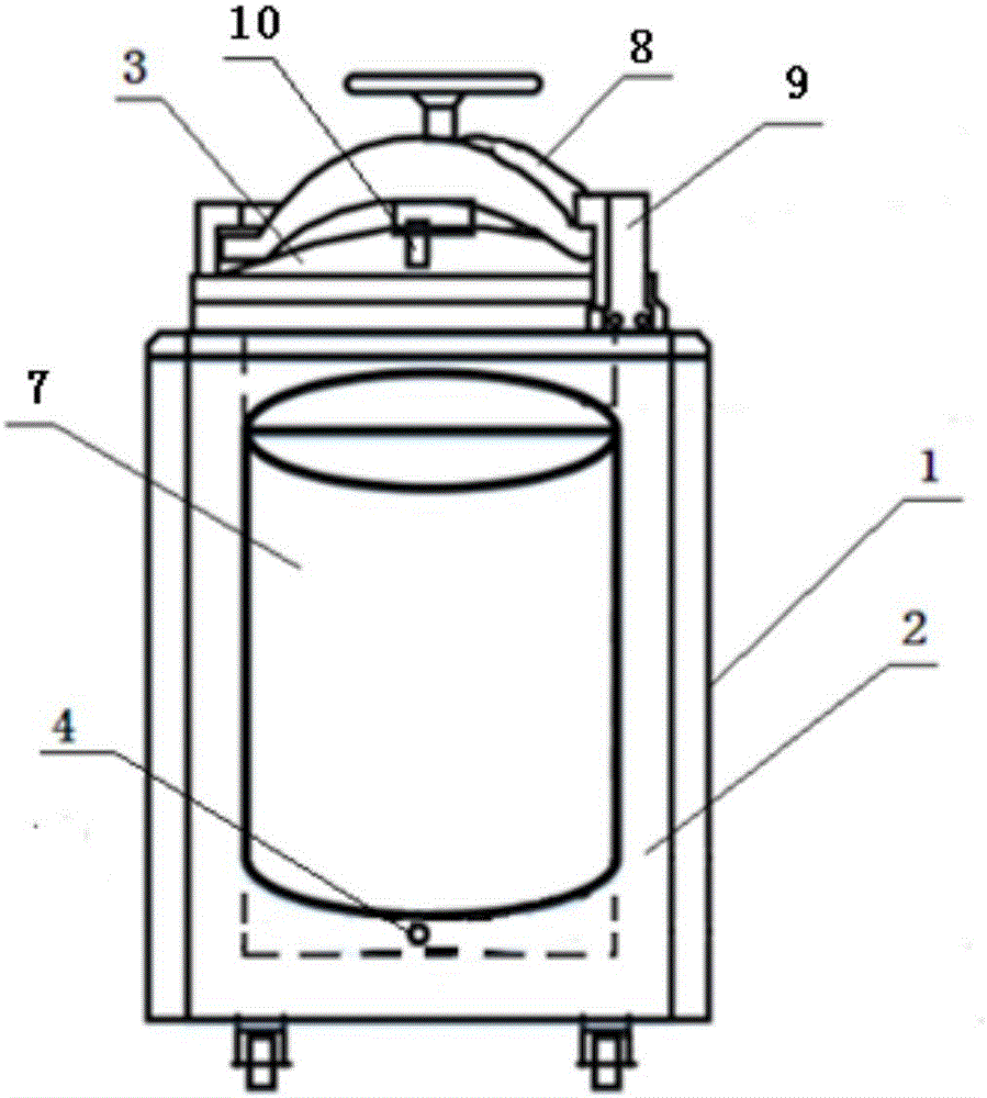
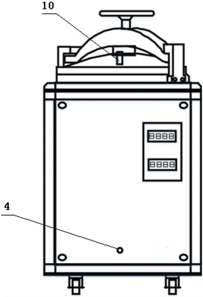
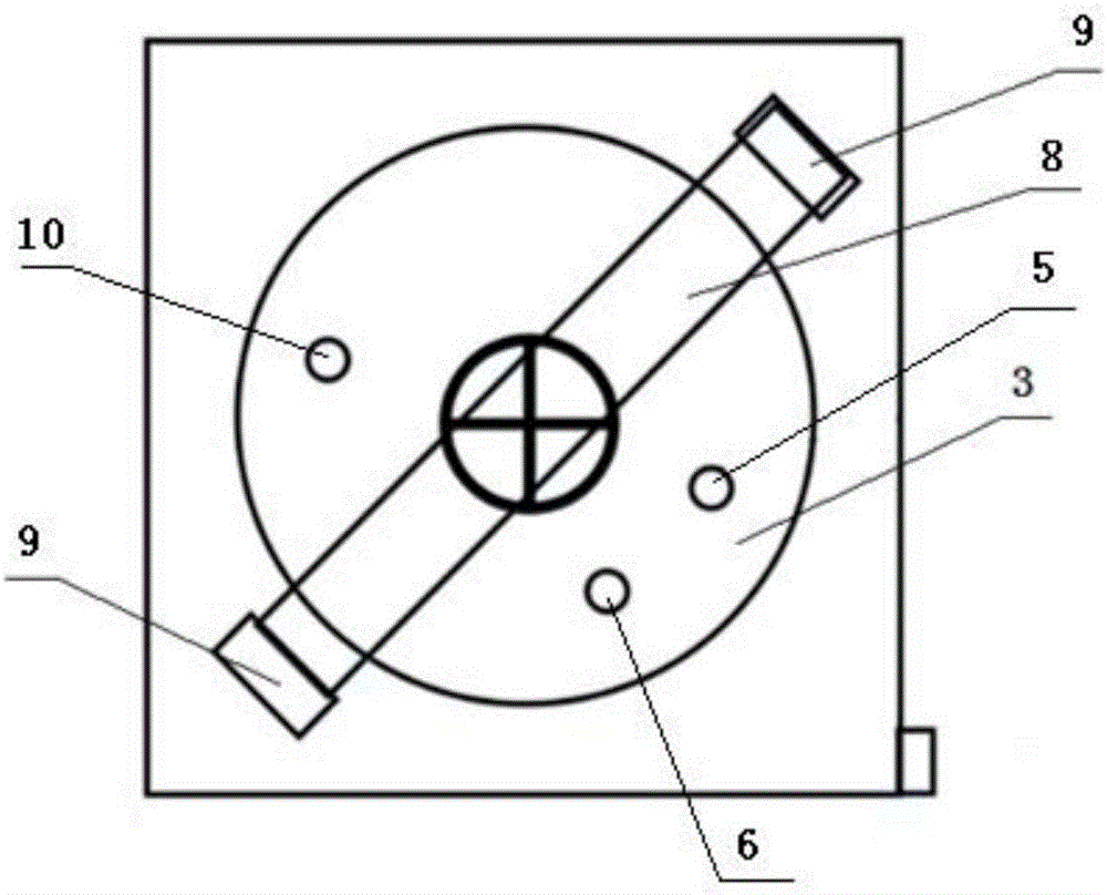
[0022] like figure 1 , image 3 As shown, the present invention provides a compost fermenter, which includes an outer tank body 1 and an inner tank body 2 built in the outer tank body 1 . Heat insulating material is filled between the outer tank body 1 and the inner tank body 2 . The top of the outer tank body 1 is connected with a top cover 3 , and the top cover 3 is connected with a gas collection pipeline 5 and an emptying pipeline 6 . An air delivery device 4 is placed on the bottom of the inner tank body 2 , and the input end of the air delivery device 4 passes through the inner tank body 2 and the outer tank body 1 .

[0023] Further, as figure 1 , figure 2 As shown, the outer tank body 1 is a cuboid structure with a circular opening on the top, the inner tank body 2 is a cylindrical structure without a cover, and the top cover 3 is a circ...


PUM


Abstract

The invention discloses a compost fermentation tank. The compost fermentation tank is characterized by comprising an outer tank body and an inner tank body, wherein the inner tank body is internally arranged in the outer tank body; the part between the outer tank body and the inner tank body is filled with a thermal insulation material; the top of the outer tank body is connected with a head cover; the head cover is connected with a gas recovery pipe and an exhaust pipe; an air supply device is arranged at the bottom of the inner tank body; and an input end of the air supply device penetrates out of the inner tank body and the outer tank body. The part between the outer tank body and the inner tank body is filled with the thermal insulation material, the air supply device is arranged at the bottom of the inner tank body, and the head cover is connected with the gas recovery pipe and the exhaust pipe, so that a compost can be fermented in proper temperature and humidity environments; the generated fermentation gas is small in concentration change amplitude; collection of the fermentation gas through the gas recovery pipe is simple and convenient, and an error caused by an environment change is reduced; meanwhile, the condition that the internal pressure of the tank body is in a safety range is ensured through the exhaust pipe; and the accuracy of online real-time measurement and laboratory detection of the fermentation gas is achieved.

Description

technical field [0001] The invention relates to a compost fermentation device, in particular to a compost fermentation tank. Background technique [0002] During the composting process of organic fertilizer, a large amount of toxic and harmful gases are produced, such as ammonia, hydrogen sulfide, sulfur dioxide, etc., which cause serious pollution to the environment. To control and reduce the toxic and harmful gases produced in the composting process, we must first know the volatilization of these gases, so how to accurately detect the volatilization of these gases is particularly important. The composting site is generally an open or semi-open factory building. According to the requirements of the composting process, ventilation, turning, etc. are required during the composting process. The environment of the composting site is harsh, with large changes in temperature and humidity. Detection is difficult. At present, there are two main methods of measuring toxic and harm...

Claims


Application Information

Patent Timeline
IPC IPC(8): C05F17/02
CPCC05F17/914C05F17/70Y02W30/40
Inventor 刘善江田野陈益山李亚星谷佳林孙昊杜颖
Owner BEIJING ACADEMY OF AGRICULTURE & FORESTRY SCIENCES
Learn More