Aerial operation platform with electronic induction safety protection device

A technology of safety protection device and aerial work platform, applied in the direction of safety device, lifting equipment safety device, lifting device, etc., can solve the problems of complex structure, occupation, physical injury, etc., to change the transmission mode, ensure personal safety, structure The effect of fewer parts

Active Publication Date: 2017-05-31
ZHEJIANG DINGLI MACHINERY CO LTD
View PDF5 Cites 5 Cited by
  • Summary
  • Abstract
  • Description
  • Claims
  • Application Information

AI Technical Summary

Problems solved by technology

[0008] However, the existing safety protection equipment realized by the mechanical protection bar has many disadvantages, for example, the sensitivity of the mechanical protection bar itself is low, and the reality is that the operator will only touch the mechanical protection bar after being squeezed The action of cutting off the power, and the squeezing action must reach a certain level to trigger the action of the mechanical protection lever. Therefore, when the mechanical protection lever works, the operator has been slightly squeezed and caused bodily injury. Therefore, the existing Poor safety of aerial work platforms with mechanical protective poles
In addition, since the mechanical protective bar straddles the left and right sides of the console, it means that the protective bar must occupy the operating space of the operator, so that the operator is limited when manipulating the various control buttons on the console, which often It is difficult to comfortably press the various buttons, thus causing operational inconvenience to the operator
[0009] At the same time, the safety protection equipment adopted by the existing aerial work platform adopts the protection rods across the two sides of the operation platform, which leads to a rather complicated structure and undoubtedly increases the cost of the product

Method used


Image

  • Aerial operation platform with electronic induction safety protection device
  • Aerial operation platform with electronic induction safety protection device
  • Aerial operation platform with electronic induction safety protection device

Examples


Embodiment Construction

[0048] The present invention will be further described below with reference to the accompanying drawings and exemplary embodiments, wherein the same reference numerals in the accompanying drawings all refer to the same components. Also, detailed descriptions of known arts will be omitted if they are unnecessary to illustrate the features of the present invention.

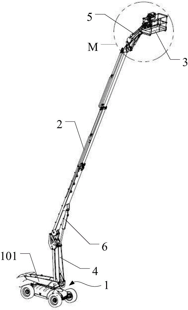
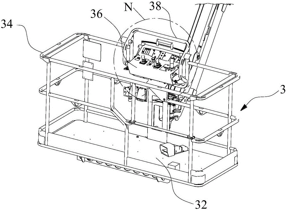
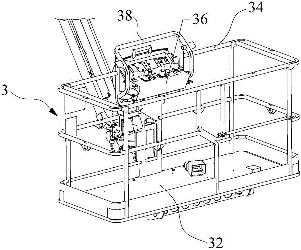
[0049] A structural schematic diagram of an aerial work platform with an electronic induction safety protection device provided by the present invention is as follows: Figure 1-16 As shown, it includes a vehicle body 1 , a telescopic transmission assembly 2 pivotally connected to the vehicle body 1 , and an operating console 3 connected to the end of the telescopic transmission assembly 2 through a telescopic connection assembly 5 .

[0050] It should be noted that the vehicle body 1 includes a vehicle frame, a drive system arranged on the vehicle frame, and a control box electrically connected to the drive system,...


PUM


Abstract

The invention relates to the field of engineering machinery, in particular to an aerial operation platform with an electronic induction safety protection device. The aerial operation platform comprises a vehicle body, an extension transmission module pivoted on the vehicle body, and a console hinged to the tail end of the extension transmission module; the console includes a baseplate, an annular fence arranged on the edge of the baseplate, and a control panel mounted on the annular fence; a fence is arranged on the edge of the control panel, and include two side fence sections respectively positioned on the left and right two sides of the control panel; the fence is provided with the electronic induction safety protection device electrically connected with the control panel; and the electronic induction safety protection device includes an optical emitter and an optical receiver matched with each other and oppositely arranged on the two side fence sections. The aerial operation platform with the electronic induction safety protection device is fewer in structural parts, simple in structure, lower in cost, more convenient to install, shorter in light ray propagation path and quicker in reaction.

Description

[0001] 【Technical field】 [0002] The invention relates to the field of engineering machinery, in particular to an aerial work equipment, and more particularly to an aerial work platform with an electronic induction safety protection device. [0003] 【Background technique】 [0004] Aerial work platform is an advanced aerial work machine, which can greatly improve the work efficiency, safety and comfort of aerial construction personnel, and reduce labor intensity. It has been widely used in developed countries. The use of aerial work platforms in my country is becoming more and more extensive, such as the initial general municipal street lamp maintenance, garden tree pruning, etc., and with the rapid development of my country's economy, engineering construction, industrial installation, equipment maintenance, plant maintenance, shipbuilding, Electricity, municipal administration, airports, communications, gardens, transportation, etc. have a growing demand for aerial work platfor...

Claims


Application Information

Patent Timeline
Patent Type & Authority Applications(China)
IPC IPC(8): B66F11/04
CPCB66F11/044B66F11/046B66F17/006G01V8/10B66C15/045
Inventor 许树根
Owner ZHEJIANG DINGLI MACHINERY CO LTD
Why Eureka
Try Eureka