Bearing ring feeder

A bearing ring and feeder technology, which is applied to conveyor objects, transportation and packaging, etc., can solve problems such as increased production costs, waste of raw materials, product bumps, etc., to improve work efficiency, reduce production costs, and avoid mutual collisions Effect

Active Publication Date: 2017-05-31
NINGBO CIXING BEARING
View PDF6 Cites 2 Cited by
  • Summary
  • Abstract
  • Description
  • Claims
  • Application Information

AI Technical Summary

Problems solved by technology

[0002] The bearing rings after the automatic processing of the machine tool are generally manually loaded. The speed of feeding and the processing speed of the bearing rings cannot be well matched, and the distance between the two bearing rings cannot be controlled. It is easy to collide with each other, which has a great impact on the appearance and machining accuracy of the bearing, and produces a large number of waste and defective products; secondly, in order for the next process to proceed normally, at least two people are required to alternately push the bearing ring to the feeding channel, which consumes a lot of time. More manpower increases the production cost, and if you accidentally use too much force, it will cause damage to the product and waste of raw materials

Method used


Image

  • Bearing ring feeder
  • Bearing ring feeder
  • Bearing ring feeder

Examples


Embodiment Construction

[0016] In order to make the technical means, creative features, goals and effects achieved by the present invention easy to understand, the present invention will be further described below in conjunction with specific illustrations.

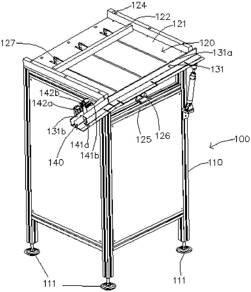
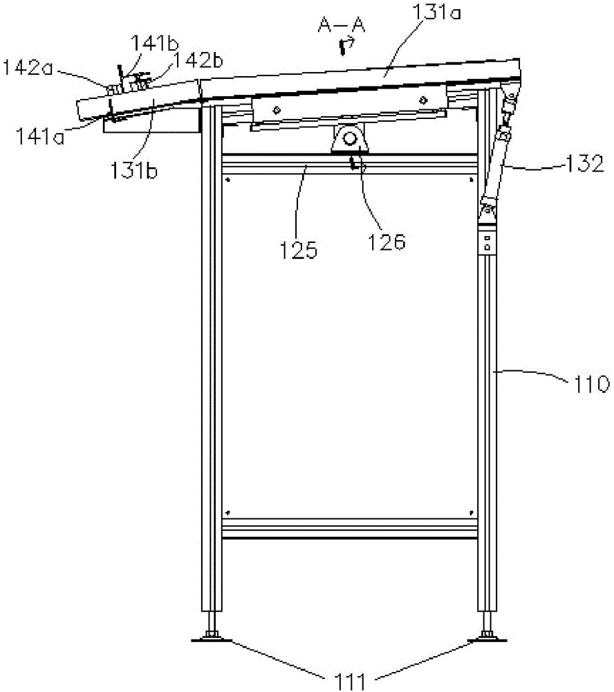
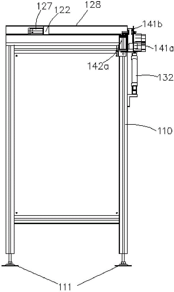
[0017] see Figure 1 to Figure 4 , shown in the figure is a bearing ring feeder 100 , including a frame 110 , a pushing device 120 , a conveying device 130 and a ring dividing device 140 . The base of the frame 110 is provided with four circular spikes 111; the conveying device 130 is arranged on one side of the frame 110, including a feeding channel 131, which can be divided into a feeding channel 131a on the frame 110 And protruding from the frame 110 portion of the sub-circle blanking channel 131b, the lowest end of the conveying blanking channel 131a can be hinged on the frame 110.

[0018] The higher end of the conveying and unloading channel 131a is provided with a push rod device that drives the inclination of the unloading channel 131. ...


PUM


Abstract

The invention discloses a bearing ring feeder which comprises a framework and an oblique storage table. The storage table is arranged on the framework, an oblique discharge channel is arranged on a side of the storage table, the lowest end of the discharge channel is hinged onto the framework, and a driving device for changing oblique angles of the discharge channel is arranged at the highest end of the discharge channel; a push device for pushing bearing rings to the discharge channel is arranged on the storage table; a ring separating device for discharging the bearing rings one by one is arranged at a discharge outlet of the discharge channel. The bearing ring feeder has the advantages that the storage table has appropriate oblique angles, so that the bearing rings can be neatly arrayed, can be separately fed and can be prevented from being collided with one another, accordingly, defective products due to collision can be reduced, and the production cost can be lowered; the distance between a pair of discharge barriers of the discharge channel can be appropriately adjusted, and accordingly the discharge channel is applicable to discharging the diversified bearing rings.

Description

technical field [0001] The invention relates to the field of mechanical production, and mainly relates to a bearing ring feeding machine. Background technique [0002] The bearing rings after the automatic processing of the machine tool are generally manually loaded. The speed of feeding and the processing speed of the bearing rings cannot be well matched, and the distance between the two bearing rings cannot be controlled. It is easy to collide with each other, which has a great impact on the appearance and machining accuracy of the bearing, and produces a large number of waste and defective products; secondly, in order for the next process to proceed normally, at least two people are required to alternately push the bearing ring to the feeding channel, which consumes a lot of time. A lot of manpower increases the production cost, and once the force is accidentally used too much, it will cause damage to the product and waste of raw materials. Contents of the invention ...

Claims


Application Information

Patent Timeline
IPC IPC(8): B65G47/82B65G47/88
CPCB65G47/82B65G47/88Y02P70/10
Inventor 张斌苏达士
Owner NINGBO CIXING BEARING
Why Eureka
Try Eureka