Eureka AIR delivers breakthrough ideas for toughest innovation challenges, trusted by R&D personnel around the world.

Locomotive and locomotive collision-proof structure for rail vehicle

A rail vehicle and anti-collision technology, applied in the field of rail transit, can solve the problems of injury to drivers and passengers, occupying a large space, no protection, etc., and achieve the effects of improving safety performance, strong anti-collision ability, and simple structure

Active Publication Date: 2017-05-31
ZHUZHOU ELECTRIC LOCOMOTIVE CO
View PDF5 Cites 10 Cited by
  • Summary
  • Abstract
  • Description
  • Claims
  • Application Information

AI Technical Summary

Problems solved by technology

The car body designed by this method will produce a collision deceleration exceeding the capacity of the human body when the collision speed is high, which will cause damage to the driver and passengers
[0005] At the same time, the above two methods can only provide a certain degree of protection for the driver and passengers during a frontal collision, but there is no protection for side collisions.
[0006] At present, there is generally no anti-collision structure on the side of the rail vehicle driver's cab at home and abroad. With the development of rail transit, the railway traffic network has become more and more complicated. Rollovers and collisions of rail vehicles occasionally occur. Therefore, drivers The collision avoidance of the side of the room is also becoming more and more important.
In addition, side windows or entrance doors are installed on the sides of existing locomotive cabs. The side windows are movable up and down, and the entrance doors are hinged and side-opening. The setting of side windows and entrance doors requires a lot of space, resulting in Unable to set hosting structure

Method used


Image

  • Locomotive and locomotive collision-proof structure for rail vehicle
  • Locomotive and locomotive collision-proof structure for rail vehicle
  • Locomotive and locomotive collision-proof structure for rail vehicle

Examples


Embodiment Construction

[0026] The present invention will be further described below in conjunction with accompanying drawing.

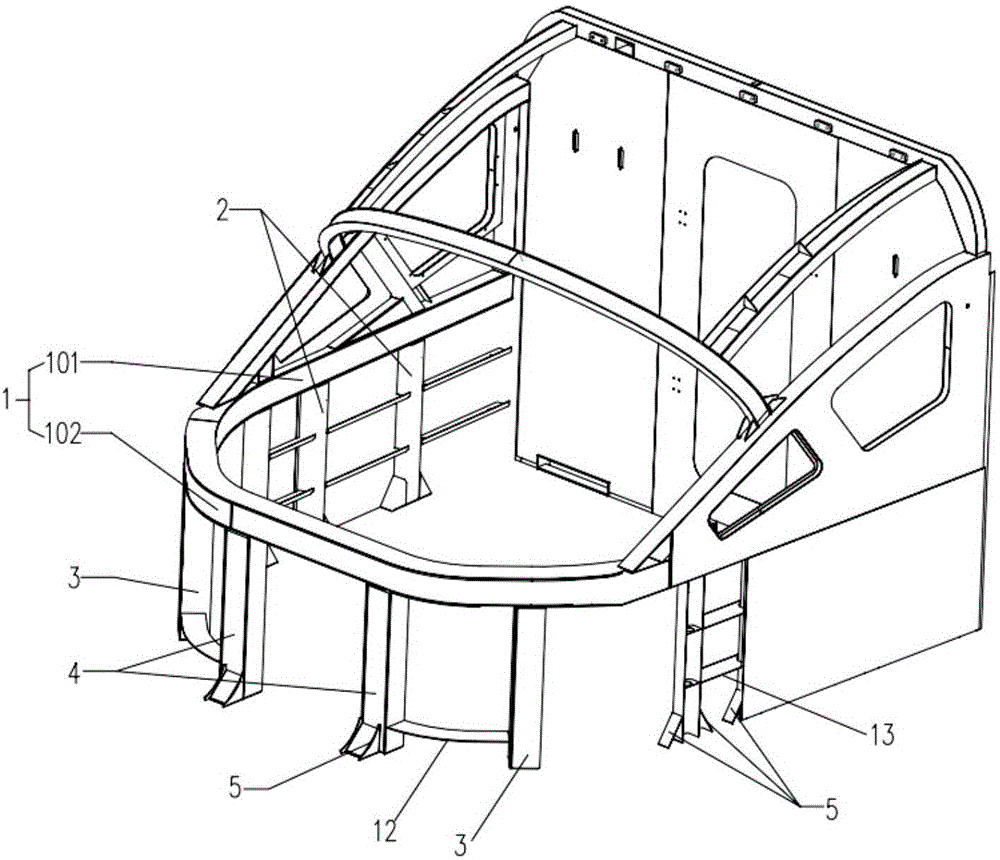
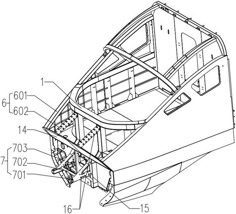
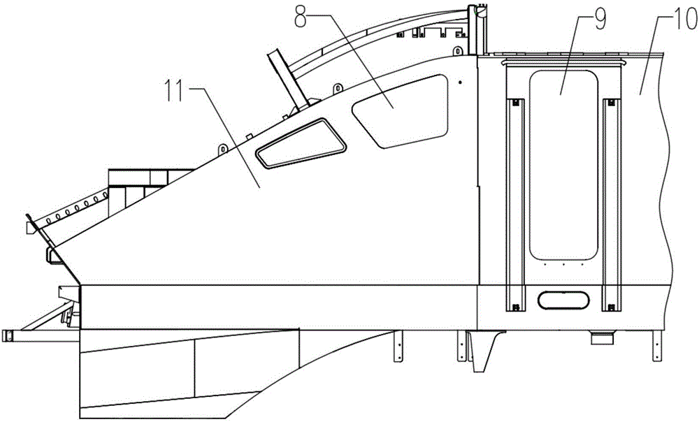
[0027] The anti-collision structure of the rail vehicle head of the present embodiment includes a front anti-collision column 4 arranged on the front end chassis of the driver's cab 11 and a corner post 3 arranged on the side of the front end chassis of the driver's cab 11. The front anti-collision column 4 and corner posts 3 are respectively distributed symmetrically along the traveling direction of the car body. The rail vehicle head anti-collision structure also includes a semi-circular anti-collision waist beam 1 and side anti-collision posts 2 arranged on the side chassis of the driver's cab 11. The anti-collision waist beam 1 is composed of a side anti-collision waist beam 101 and a front window anti-collision waist beam 102, and the side anti-collision waist beam 101 is fixed on the top of the side anti-collision pillar 2; Crash the waist beam 102 and be fixed on the...


PUM


Abstract

The invention relates to a locomotive and a locomotive collision-proof structure for a rail vehicle. The locomotive collision-proof structure comprises front collision-proof columns and corner columns, and the front collision-proof columns and the corner columns are arranged on a chassis at the front end of a driver's cab and respectively symmetrically distributed along a vehicle advancing direction. The locomotive collision-proof structure further comprises a semicircular collision-proof waist beam and lateral collision-proof columns on a lateral chassis of the driver's cab, and the collision-proof waist beam is formed by connection of a lateral collision-proof waist beam and a front window collision-proof waist beam, the lateral collision-proof waist beam is fixed to tops of the lateral collision-proof columns, and the front window collision-proof waist beam is fixed to tops of the front collision-proof columns and the corner columns. The locomotive collision-proof structure for the rail vehicle is simple in structure and great in collision-proof performance; by synergistic effects of the front collision-proof structure and the lateral collision-proof structure, the locomotive collision-proof structure is capable of effectively dealing with front collision and also has a lateral collision prevention function, so that safety of the vehicle is improved. The probability of direct collision destroy of the front collision-proof structure is low, and high safety is realized.

Description

technical field [0001] The invention belongs to the field of rail traffic, and in particular relates to an anti-collision structure for a rail vehicle head and a front equipped with the anti-collision structure for a rail vehicle head. Background technique [0002] The main function of the locomotive body is to carry equipment, transmit traction and braking force. And the function of the locomotive driver's cab as one of the important components of the car body not only provides a place for activities for the drivers and passengers, but also provides a safety barrier for the drivers and passengers. [0003] The European standard EN 15227 describes that the front part of the car body should have structural passive safety, and an energy absorbing area within a certain range is set at the end of the car body, that is, when the car body collides, the structure of the car body and the anti-climber structure are used. Deformation is used to absorb energy. For the car body designe...

Claims


Application Information

Patent Timeline
IPC IPC(8): B61D17/00
CPCB61D17/00
Inventor 闵阳春杨小荣张兴陈尚强金希红
Owner ZHUZHOU ELECTRIC LOCOMOTIVE CO
Why Eureka
Eureka Blog
Learn More