Automobile self-rescuer

A self-rescuer and car trapping technology, which is applied to vehicle parts, anti-skid devices, tire parts, etc., can solve problems such as difficult disassembly, road damage, time-consuming and labor-intensive problems, and achieve fast assembly and disassembly, safe escape from potholes, and use convenient effect

Active Publication Date: 2018-06-26
天津市博安塑胶制品有限公司
View PDF5 Cites 0 Cited by
  • Summary
  • Abstract
  • Description
  • Claims
  • Application Information

AI Technical Summary

Problems solved by technology

[0004] There are many kinds of tire anti-skid devices on the market, the most common ones are iron chains, tendon chains or rubber chains made of anti-skid chains. The tires are equipped with anti-skid chains to generate momentary pressure on the ground and increase the friction with the road surface to prevent slipping. The function is to increase the safety performance of the vehicle; the disadvantages are that it is difficult to disassemble and assemble, the weight is heavy, and the tire wear and damage to the road surface are serious, which will affect the safety of the vehicle to a certain extent; especially in the alpine regions of Northeast and Northwest my country, Due to the long ice and snow period in winter, various vehicles have tens of thousands of traffic accidents caused by wet roads, pits, and covered cars every year, but the anti-skid chains in the prior art have an unsatisfactory anti-skid effect in practical applications; Car or pit self-rescue measures are not perfect, and the installation and disassembly of anti-skid chains and self-rescue equipment is cumbersome, time-consuming and laborious

Method used


Image

  • Automobile self-rescuer
  • Automobile self-rescuer
  • Automobile self-rescuer

Examples


Embodiment Construction

[0022] In order to further understand the invention content, characteristics and effects of the present invention, the following examples are given, and detailed descriptions are as follows in conjunction with the accompanying drawings:

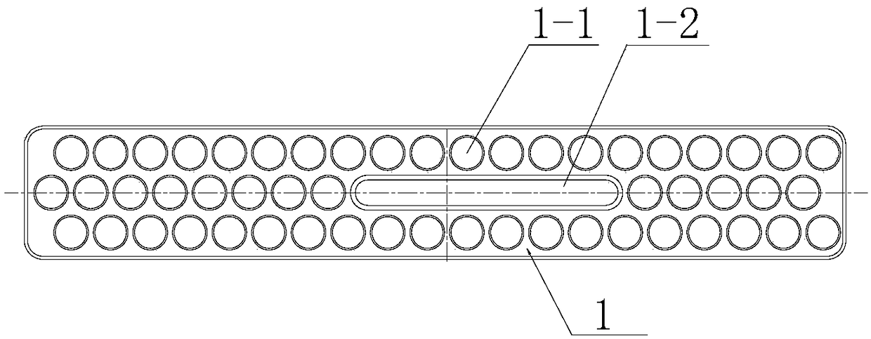
[0023] see Figure 1 to Figure 4 , a car trap self-rescuer, comprising a bearing plate 1, the bearing plate is provided with anti-slip protrusions 1-1,

[0024] The upper surface of the bearing plate is divided into a tire bearing area 10 and a supporting area 20;

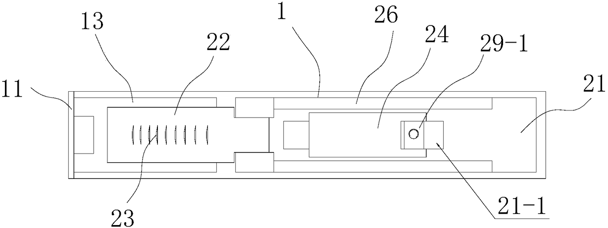
[0025] One end of the bearing plate tire bearing area is provided with a limiting platform 11, and the positioning baffle 13 is hinged by a baffle pin 12 on the bearing plate near the position of the limiting platform; On the arc surface, the upper end of the positioning baffle is provided with a bend 14 toward the side of the hub 30; the bending can be used as an integral structure of the positioning baffle, or can be made into a foldable structure; the upper part of the support...


PUM


Abstract

The invention relates to a self-rescuer for a trapped automobile. The self-rescuer for the trapped automobile comprises a bearing plate; the upper surface of the bearing plate is divided into a tire bearing area and a supporting area; one end part of the tire bearing area of the bearing plate is provided with a limiting platform; through a baffle pin, a locating baffle is hinged on the bearing plate close to the limiting platform; the upper end part of the locating baffle is provided with a bend facing a lateral direction of a hub; a locating slide plate is assembled on the upper surface of the supporting area of the bearing plate; through a hinging shaft, a movable baffle is hinged on the locating slide plate close to the tire bearing area; a locating groove is formed in the external side surface of the locating baffle; a supporting plate is also hinged on the locating slide plate in a sliding manner; the supporting plate is mounted on the bearing plate through a tightening piece in an adjustable manner; and the upper end of the supporting plate is clamped in the locating groove. The self-rescuer for the trapped automobile has the advantages that the self-rescuer is simply structured and convenient to mount and use, the automobile can be effectively rescued while being in slipping, covering and trapping, the self-rescuer is convenient to assemble and disassemble and time-saving and labor-saving, the driving safety is enhanced, the accidents are reduced and so on.

Description

technical field [0001] The invention belongs to the technical field of automobile trap self-rescue technical equipment, and in particular relates to a car trap self-rescue device. Background technique [0002] With the development of society, automobiles bring great convenience to people's travel; with the continuous development of the automobile industry, people can't help but demand the safety and comfort of driving automobiles, and also require the versatility of automobiles; but when automobiles When driving in the desert or on a muddy dirt road, due to the influence of factors such as weather conditions or geographical environment, the tires of the car often fall into sand pits or dirt pits, and at this time they cannot drive away and are trapped; in winter, especially in the north In the icy and snowy climate, the road is covered with snow and the ground is slippery. Many cars will encounter the problem of slippery roads, and accidents often occur. [0003] During the...

Claims


Application Information

Patent Timeline
Patent Type & Authority Patents(China)
IPC IPC(8): B60C27/00
CPCB60C27/00
Inventor 只云清只珣泽
Owner 天津市博安塑胶制品有限公司
Why Eureka
Try Eureka