Anti-impact flexible joint suitable for mechanical arm
A flexible joint and impact-resistant technology, applied in the field of robotics, can solve the problems of complex structure, small flexibility, and large volume of flexible realization mechanisms, and achieve the effects of compact joint structure, good impact resistance characteristics, large load and self-weight ratio
- Summary
- Abstract
- Description
- Claims
- Application Information
AI Technical Summary
Problems solved by technology
Method used
Image
Examples
specific Embodiment approach 1
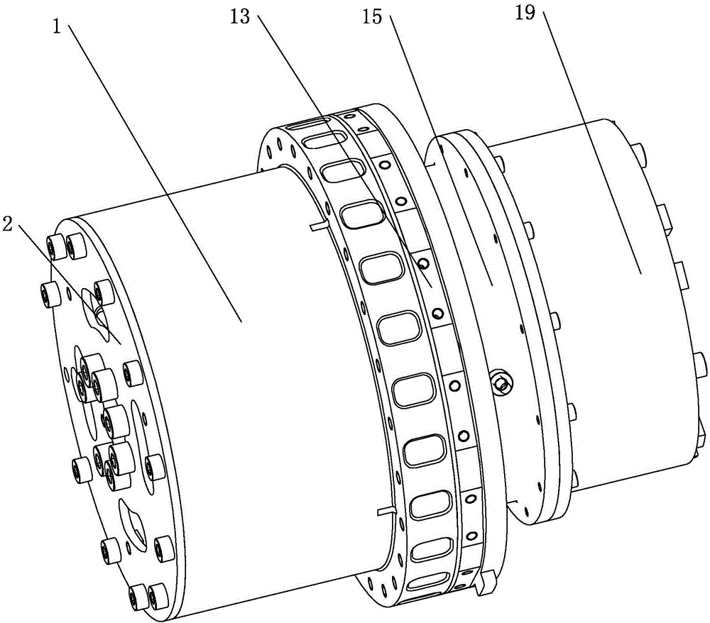
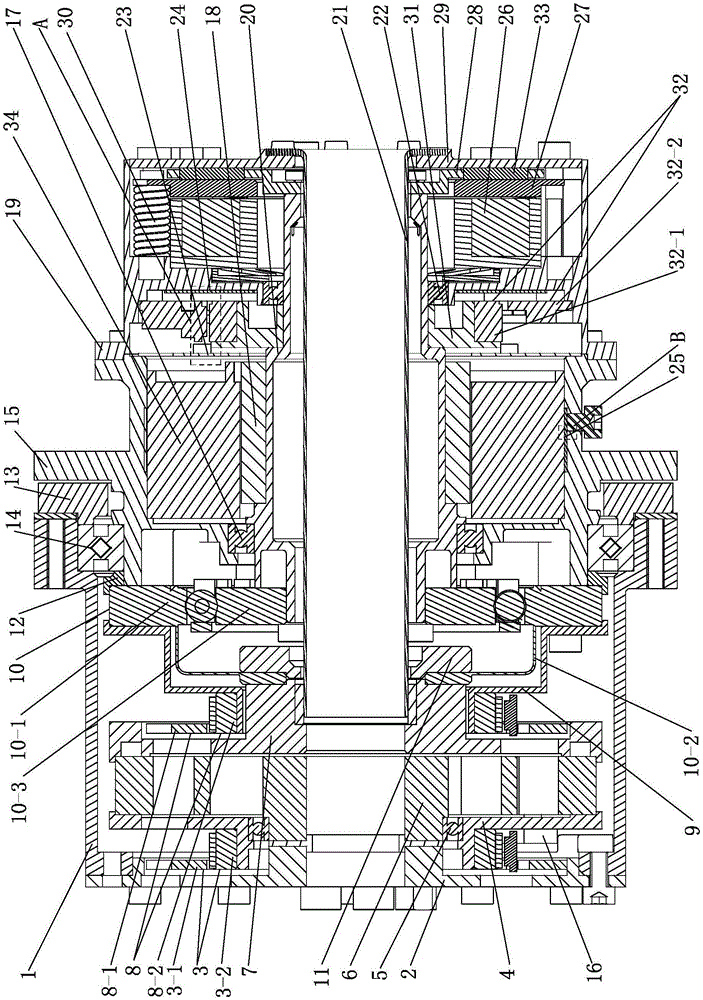
[0022] Specific implementation mode one: combine figure 1 , figure 2 , Figure 5 and Figure 6Explain, an impact-resistant flexible joint suitable for a mechanical arm, which includes a drive transmission system, a sensor system, and a power-off brake. The drive transmission system includes a joint output end shell 1, a joint input end shell 15, and an output end cover 2 , limit block 16, deep groove ball bearing 1 (6706) 5, series elastic body 6, connecting flange 7, harmonic reducer 10, flexible wheel lock nut 11, deep groove ball bearing 2 (6707) 17, Cross roller bearing (RA7008) 14, bearing outer ring baffle 13, bearing inner ring baffle 12, C-shaped ring 25, hollow cable shaft 21, deep groove ball bearing three (6705) 22 and motor, the motor includes Motor rotor 18, motor stator 34 and motor central shaft 20, described sensing system comprises the first joint position magnetic encoder 3, the first magnetic ring holder 4, the second joint position magnetic encoder 8, t...
specific Embodiment approach 2
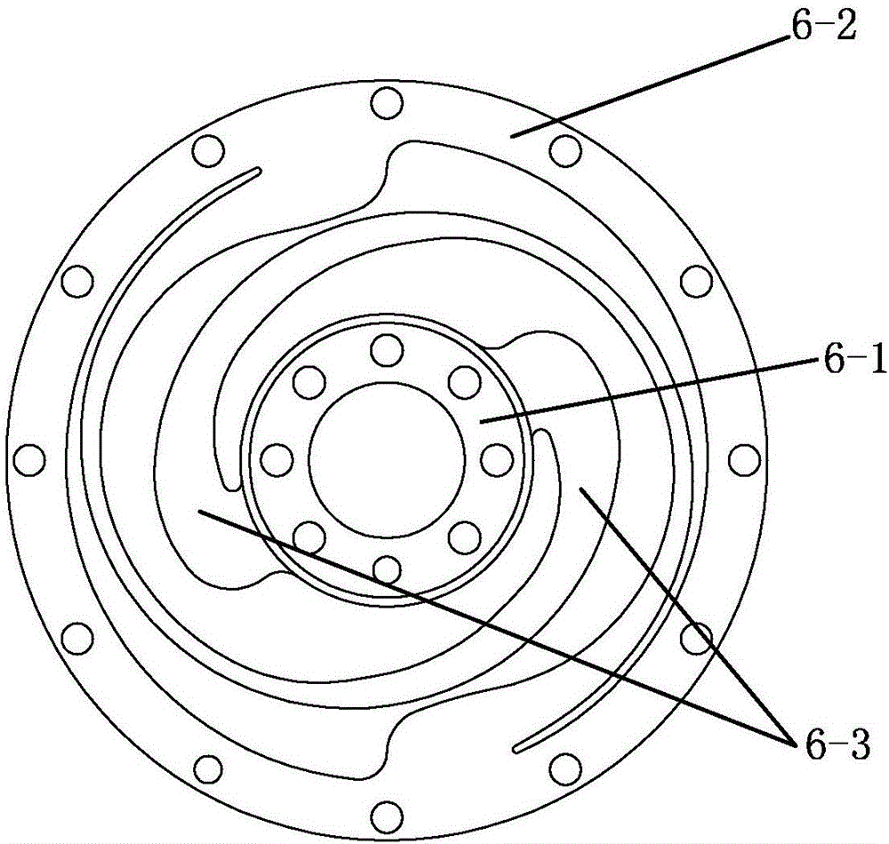
[0025] Specific implementation mode two: combination Figure 2 ~ Figure 4 To illustrate, the impact-resistant flexible joint suitable for mechanical arms described in the first embodiment, the series elastic body 6 includes an inner ring 6-1, an outer ring 6-2 and two sets of flexible beams 6-3, the The inner ring 6-1 and the outer ring 6-2 are arranged concentrically, and two groups of flexible beams 6-3 are symmetrically connected between the inner ring 6-1 and the outer ring 6-2 along the circumferential direction, and the inner ring 6-1 (through bolts) It is fixedly connected with the output end cover 2, the outer ring 6-2 is fixedly connected with the limit block 16 and the first magnetic ring holder 4 (through bolts respectively), and the deep groove ball bearing-5 is installed on the inner ring 6- 1 and the first magnetic ring fixing frame 4, the outer ring 6-2 (through bolts) is respectively (through bolts) fixedly connected with the limit block 16 and the outer ring f...
specific Embodiment approach 3
[0027] Specific implementation mode three: combination figure 2 To illustrate, the specific embodiment 1 or 2 describes an impact-resistant flexible joint suitable for a mechanical arm. The first joint position magnetic encoder 3 includes a first joint circuit board 3-1 and a first joint magnetic ring 3- 2. The first joint circuit board 3 - 1 is fixedly connected to the output end cover 2 , and the first joint magnetic ring 3 - 2 is fixedly connected to the first magnetic ring fixing frame 4 .
PUM
 Abstract
Description
Claims
Application Information
 - R&D Engineer
- R&D Manager
- IP Professional
- Industry Leading Data Capabilities
- Powerful AI technology
- Patent DNA Extraction
Browse by: Latest US Patents, China's latest patents, Technical Efficacy Thesaurus, Application Domain, Technology Topic, Popular Technical Reports.
© 2024 PatSnap. All rights reserved.Legal|Privacy policy|Modern Slavery Act Transparency Statement|Sitemap|About US| Contact US: help@patsnap.com


