
Robot joint structure and robot

A technology of robot joints and joints, applied in the direction of structural connection, manipulator, mechanical equipment, etc., can solve the problems of large volume of robot joint structure, and achieve the effect of reducing volume and weight, reducing axial size, and compact joint structure

Active Publication Date: 2021-12-31
UBTECH ROBOTICS CORP LTD
View PDF8 Cites 0 Cited by
  • Summary
  • Abstract
  • Description
  • Claims
  • Application Information

AI Technical Summary

Problems solved by technology

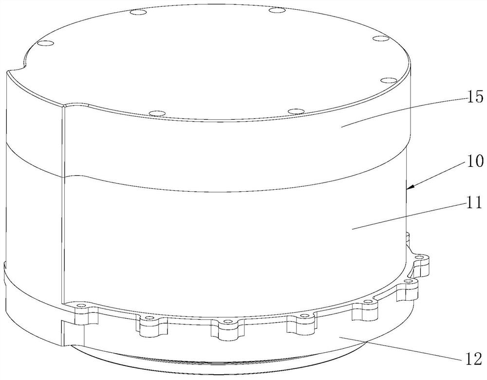
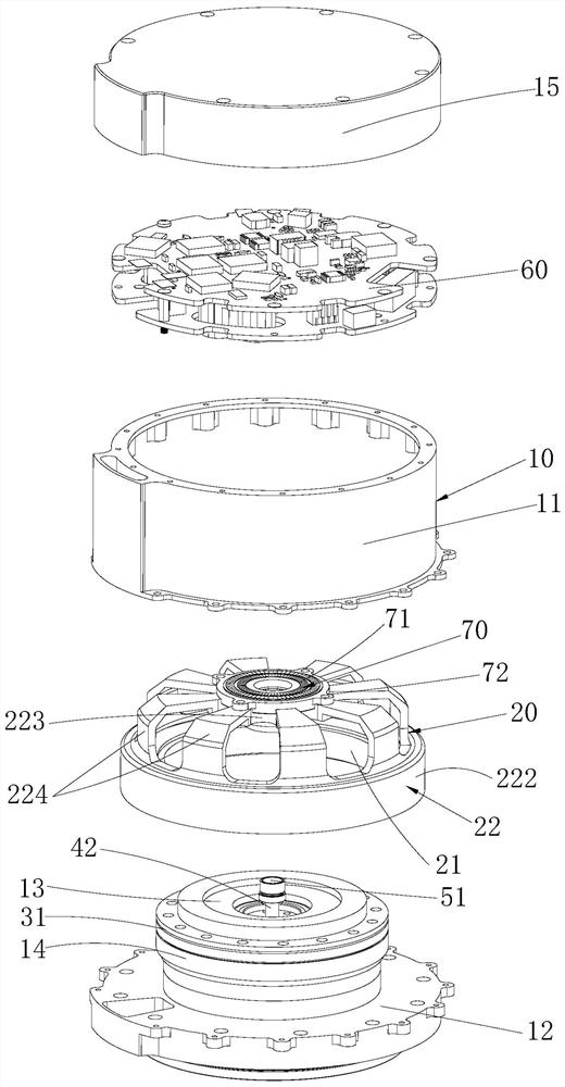
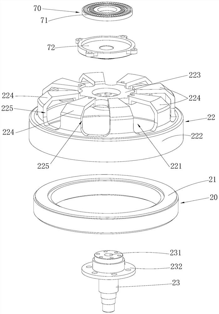
[0003] The purpose of the embodiments of the present application is to provide a robot joint structure and a robot to solve the technical problem of large volume of the existing robot joint structure

Method used


Image

  • Robot joint structure and robot
  • Robot joint structure and robot
  • Robot joint structure and robot

Examples


Embodiment Construction

[0033] In order to make the technical problems, technical solutions and beneficial effects to be solved, the present application will be described in detail below with reference to the accompanying drawings and examples. It should be understood that the specific embodiments described herein are intended to explain the present application and is not intended to limit the present application.

[0034] In the description of the embodiments of the present application, it is to be understood that the terms "length", "width", "upper", "lower", "front", "post", "left", "right", "vertical "," Horizontal "," top "," bottom "" internal "," outside ", etc., is based on the orientation or positional relationship shown in the drawings, which is intended to facilitate the description of the present application and simplification. Description, rather than indicating or implying that the device or element must have a particular orientation, constructing and operating in a particular direction, an...


PUM


Abstract

The application belongs to the technical field of humanoid service robots, and relates to a robot joint structure and a robot. In the joint structure of the robot, the motor assembly adopts the form of an outer rotor, the rotor is sleeved outside the stator, and the rotor is fixed with a motor shaft. The wave generator in the harmonic reducer is installed on the motor shaft, the flexible spline is driven by the wave generator and meshes with the rigid spline, and the output shaft of the joint is fixed on the flexible spline. When working, the motor shaft drives the wave generator to rotate at high speed, and the wave generator makes the flexible spline produce flexible deformation, the flexible spline and the rigid spline are meshed for transmission, and the power is output through the joint output shaft for low-speed rotation. The output encoder is used to detect the rotation angle of the joint output shaft. The joint structure of the robot is compact, the axial dimension is reduced, the volume and weight are both reduced, and it is suitable for the lightweight and compact layout of the robot.

Description

Technical field [0001] The present application belongs to the technical field of class human service robot, involving a robot joint structure and robot. Background technique [0002] At present, the traditional robot joint structure is an axial docking reducer using the motor assembly, which makes the axial dimension of the robot joint structure, and the space utilization is insufficient, resulting in large volume, weight weight. Inventive content [0003] The purpose of the present application embodiment is to provide a robot joint structure and robot to address the technical problems of existing robot joint structural volume. [0004] The present application embodiment provides a robot joint structure, including: [0005] case; [0006] The motor assembly includes a stator provided in the housing, a rotor outer outer portion of the stator, and a motor shaft that is fixed to the rotor; [0007] The harmonic reducer includes a rigid wheel fixed to the stator, a wave generator mo...

Claims


Application Information

Patent Timeline
Patent Type & Authority Patents(China)
IPC IPC(8): B25J17/00B25J17/02B25J9/10B25J9/12
CPCB25J17/00B25J17/02B25J9/126B25J9/10B25J9/1025H02K11/215H02K7/116H02K11/22F16H49/001F16H57/021F16H2057/02086F16H2057/02069F16H57/02F16H2057/02034F16H2057/02073H02K7/088
Inventor 李建丁宏钰李友朋庞建新熊友军
Owner UBTECH ROBOTICS CORP LTD
Learn More