Chipping removal, tapping and clamping device

A technology of clamping device and support frame, which is applied in the direction of clamping device, positioning device, clamping, etc., and can solve the problems of inconvenience and stability, low tapping precision, and low efficiency

Inactive Publication Date: 2017-05-31
LIUZHOU CITY LONGCHEN AXLE PARTS MFG
View PDF7 Cites 0 Cited by
  • Summary
  • Abstract
  • Description
  • Claims
  • Application Information

AI Technical Summary

Problems solved by technology

[0003] The purpose of the present invention is to provide a chip removal tapping and clamping device. The technical problem to be solved is: it is not convenient to stabilize the irregular workpiece when tapping, the tapping precision is low and the efficiency is low; it is inconvenient to remove waste

Method used


Image

  • Chipping removal, tapping and clamping device
  • Chipping removal, tapping and clamping device

Examples


Embodiment Construction

[0013] The principles and features of the present invention are described below in conjunction with the accompanying drawings, and the examples given are only used to explain the present invention, and are not intended to limit the scope of the present invention.

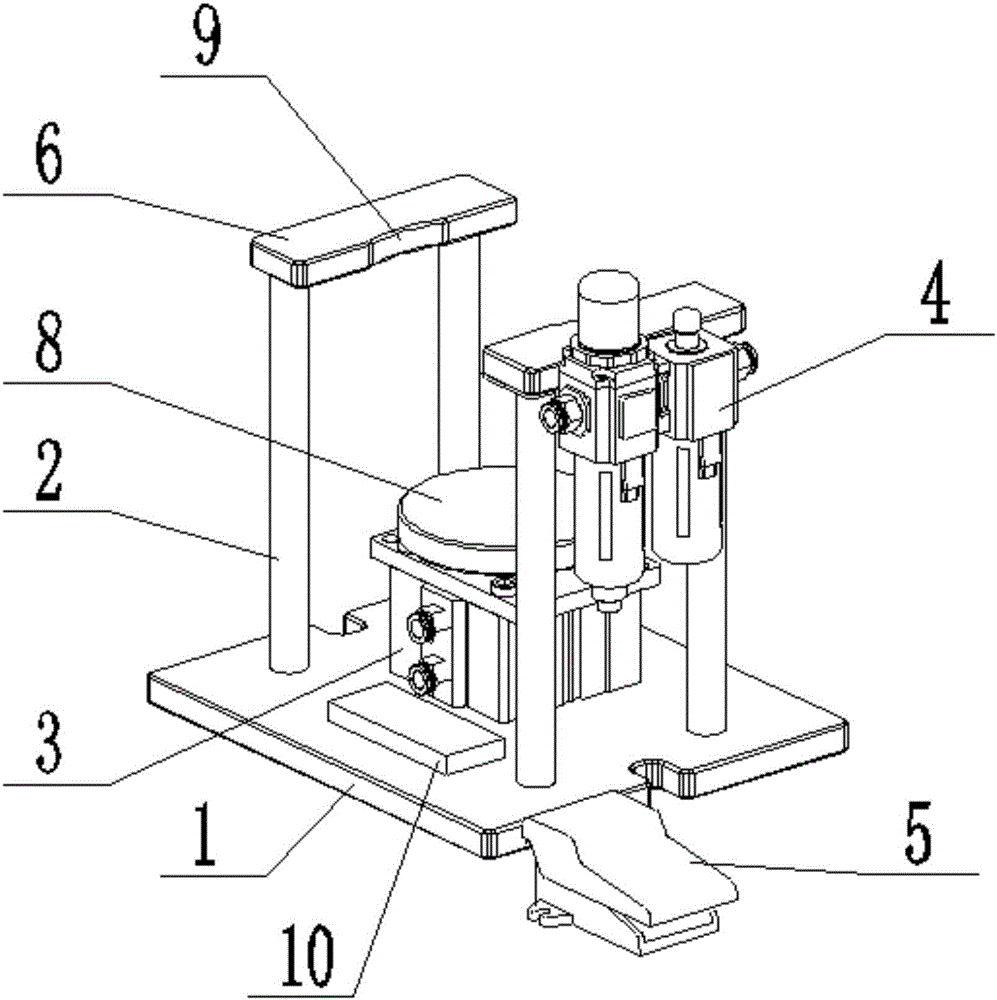
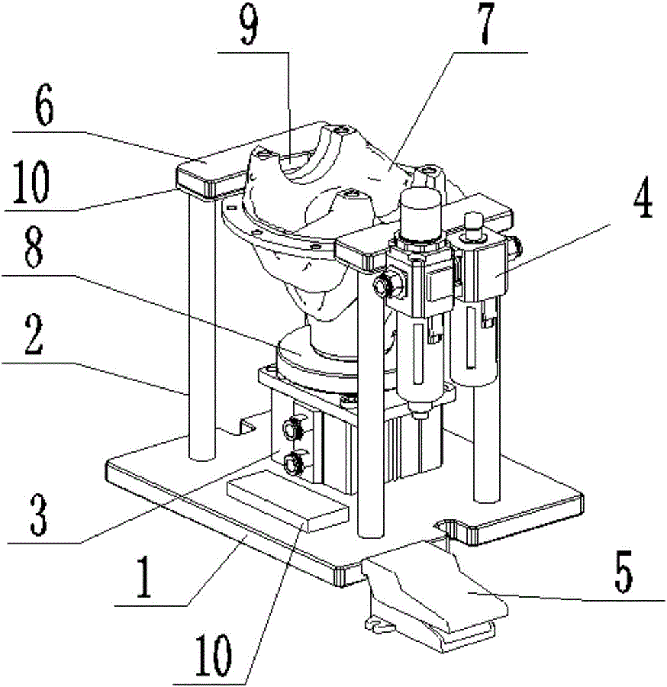
[0014] Such as figure 1 and figure 2 As shown, a chip removal tapping clamping device includes a base 1, two support frames 2, a pneumatic cylinder 3, an air valve 4 and a pedal switch 5, and the two support frames 2 are respectively fixed on the On both sides of the upper end of the base 1, the upper ends of the two support frames 2 are fixedly provided with stoppers 6; the pneumatic cylinder 3 is fixedly placed on the upper end of the base 1, and is between the two support frames The output shaft of the pneumatic cylinder 3 is at its upper end, and the upper end of its output shaft is provided with a push-up block 8 for placing the workpiece 7, and the output shaft of the pneumatic cylinder 3 telescopically driv...


PUM


Abstract

The invention relates to a chipping removal, tapping and clamping device. The chipping removal, tapping and clamping device comprises a base, two support frames, a pneumatic cylinder, a pneumatic valve and a pedal switch. The two support frames are correspondingly fixed to the two sides of the upper end of the base. Check blocks are correspondingly and fixedly arranged at the upper ends of the two support frames. The pneumatic cylinder is fixedly arranged at the upper end of the base. An output shaft of the pneumatic cylinder is located at the upper end of the pneumatic cylinder. An upper push block for containing a machining piece is arranged at the upper end of the output shaft of the pneumatic cylinder. The output shaft of the pneumatic cylinder extends and contracts to drive the upper push block and the machining piece to move vertically. The pneumatic valve is fixedly arranged on one of the support frames and communicates with the pneumatic cylinder through a gas pipe. The pneumatic valve communicates with an external gas source through the gas pipe. The pedal switch is arranged on one side of the base. The control end of the pneumatic valve is connected with the pedal switch through a circuit. An electroproduction magnetic device is arranged at the upper end of the base and connected with the pedal switch through a circuit. Compared with the prior art, by the adoption of the chipping removal, tapping and clamping device, stabilizing and tapping of irregular workpieces are achieved, the tapping accuracy is high, the efficiency is high, and waste chippings are removed conveniently.

Description

technical field [0001] The invention relates to a chip removal tapping clamping device. Background technique [0002] In the prior art, tapping irregular workpieces is inconvenient for stabilizing, and the tapping precision and efficiency are low; it is inconvenient to remove waste chips. Contents of the invention [0003] The purpose of the present invention is to provide a chip removal tapping and clamping device. The technical problem to be solved is: it is not convenient to stabilize the irregular workpiece when tapping, the tapping precision is low and the efficiency is low; it is inconvenient to remove waste. [0004] The technical solution of the present invention to solve the above-mentioned technical problems is as follows: a chip removal tapping clamping device, including a base, two support frames, a pneumatic cylinder, an air valve and a pedal switch, and the two support frames are respectively fixed on On both sides of the upper end of the base, the upper en...

Claims


Application Information

Patent Timeline
Patent Type & Authority Applications(China)
IPC IPC(8): B23Q3/08B23Q11/00
CPCB23Q3/08B23Q11/0064B23Q2703/04B23Q2703/12
Inventor 李耀敏
Owner LIUZHOU CITY LONGCHEN AXLE PARTS MFG
Why Eureka
Try Eureka