Eureka AIR delivers breakthrough ideas for toughest innovation challenges, trusted by R&D personnel around the world.

Two-chamber automatic wire patching system and method

An automatic, cabin technology, applied in the direction of manufacturing tools, welding equipment, arc welding equipment, etc., can solve the problems of wire wave deformation, increase the difficulty of parts processing, low efficiency, etc., to reduce labor intensity, shorten gas cleaning time, The effect of improving production efficiency

Active Publication Date: 2022-07-05
青岛卓思三维智造技术有限公司
View PDF7 Cites 0 Cited by
  • Summary
  • Abstract
  • Description
  • Claims
  • Application Information

AI Technical Summary

Problems solved by technology

However, the heavy weight of a single reel has the following disadvantages: firstly, the internal space of the equipment needs to be large enough, which is not suitable for small and medium-sized equipment; secondly, when assembling the reel, due to the heavy weight, it must rely on a booster device, which makes the equipment more complicated; in addition, Since the metal wire has a pre-tightening force during winding, the larger the wire reel, the greater the pressure on the inner wire, which is easy to cause the wire to have wave deformation, which seriously affects the stability during forming.
When processing large-scale parts, the weight of the parts reaches several to dozens of wire reels, and the use of open hatches to supplement materials will lead to low efficiency; at the same time, due to the long time for adjusting the atmosphere chamber when changing wires, the temperature during the manufacturing of parts It will reduce the quality of the parts at the junction of front and rear wire replacement, which will increase the difficulty of processing subsequent parts and greatly increase the working time and cost.

Method used

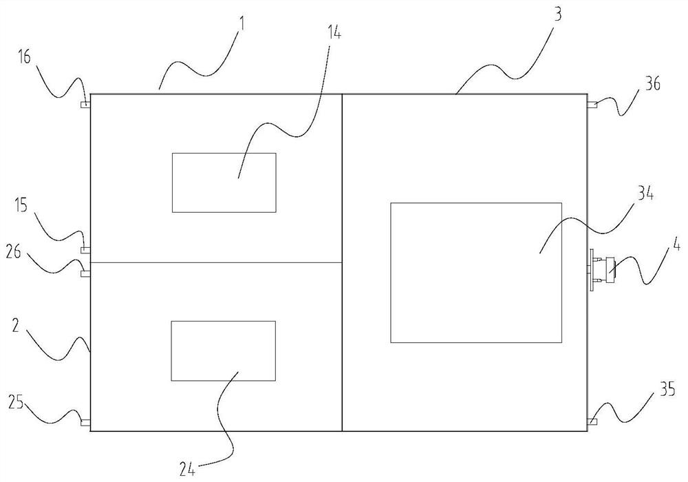
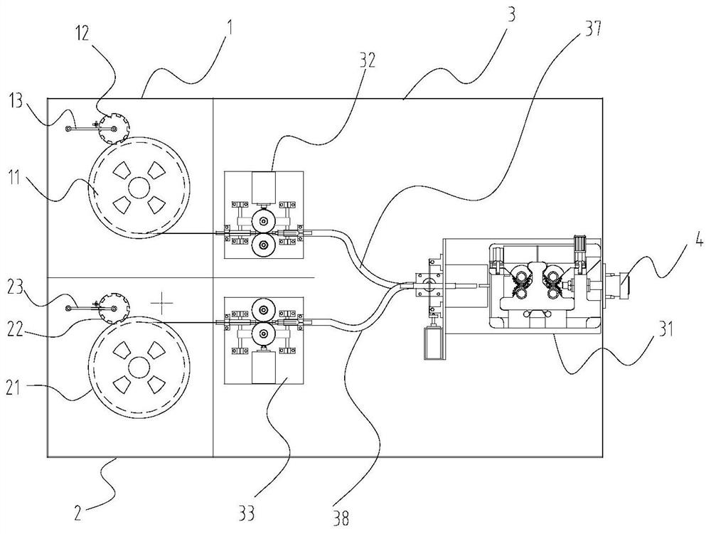
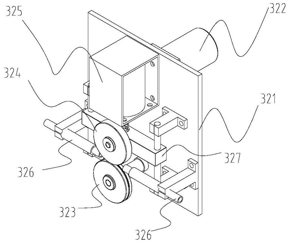

Image

  • Two-chamber automatic wire patching system and method
  • Two-chamber automatic wire patching system and method
  • Two-chamber automatic wire patching system and method

Examples


Embodiment Construction

[0031] Hereinafter, the present invention will be specifically described through exemplary embodiments. It should be understood, however, that elements, structures and features of one embodiment may be beneficially combined in other embodiments without further recitation.

[0032] In the description of the present invention, it should be noted that the terms "inside", "outside", "upper", "lower", "front", "rear", etc. used in the present invention indicate the orientation or positional relationship as Based on the attached figure 1 The shown positional relationship is only for the convenience of describing the present invention and simplifying the description, rather than indicating or implying that the indicated device or element must have a specific orientation, be constructed and operated in a specific orientation, and therefore should not be construed as a limitation of the present invention . Furthermore, the terms "first", "second", and "third" are used for descriptive...


PUM


Abstract

The present invention provides a two-chamber automatic wire patching system and a method thereof. The system is used for the additive manufacturing of electric arc, laser and plasma arc fuses, and includes a wire feeder cabin and a wire reel cabin that can provide metal wires for the wire feeder cabin. , the wire reel compartment includes two side-by-side arrangement, namely the first wire reel compartment and the second wire reel compartment, the first wire reel compartment and the second wire reel compartment are respectively connected to the wire feeder compartment; the first wire reel compartment is installed in the There is a replaceable first wire reel on which metal wire is coiled; a replaceable second wire reel is installed in the second wire reel cabin, and metal wire is coiled on the second wire reel; A wire feeder with an external welding torch interface is arranged in the wire machine compartment. A wire feed selection device is arranged between the wire feeder and the wire reel compartment. The wire feed selection device is selected as the wire feeder in the first wire reel and the second wire reel. Wire feeding to achieve automatic wire change between the first wire reel compartment and the second wire reel compartment; the method uses the system. The present invention can realize the uninterrupted supply of materials without destroying the working atmosphere of the sealed chamber.

Description

technical field [0001] The invention relates to the field of metal additive manufacturing, in particular to a wire patching process of two compartments in metal additive manufacturing. Background technique [0002] Metal direct deposition additive manufacturing technology refers to a technology that uses a heat source to melt incoming metal materials in an inert atmosphere or a vacuum environment, and accumulates them layer by layer according to a pre-planned path to prepare metal parts. In metal direct deposition additive manufacturing technology, laser or arc additive equipment requires a closed gas shield to maintain an inert gas environment, and electron beam additive equipment requires a vacuum chamber. [0003] At present, in the metal direct deposition additive manufacturing technology, the raw materials fed in are mainly powder and wire. When using wire as the raw material, the wire usually needs to be wound on the reel. Before the parts are processed, the wire stor...

Claims


Application Information

Patent Timeline
Patent Type & Authority Patents(China)
IPC IPC(8): B23K9/133B23K9/04
CPCB23K9/04B23K9/133B23K9/1336
Inventor 朱木兵锁红波邢明
Owner 青岛卓思三维智造技术有限公司
Why Eureka
Eureka Blog
Learn More