
Synchronous punching device in internal high-pressure forming mold

A technology of punching device and forming die, which is applied in the field of pipe fittings processing, can solve the problems of low processing efficiency, increase of production cost, and increase of clamping times, and achieve the effects of good flexibility of use, improvement of reliability and processing accuracy

Active Publication Date: 2017-05-31
BAOLONG ANHUI AUTO PARTS
View PDF6 Cites 1 Cited by
  • Summary
  • Abstract
  • Description
  • Claims
  • Application Information

AI Technical Summary

Problems solved by technology

[0003] The existing in-mold punching is to install one punching cylinder in one working direction, so it is often necessary to install multiple punching cylinders, but when the punching directions are different and the hole distance is small, there is not enough space to install the required cylinders Quantity, so the existing in-mold punching technology has limitations
The above-mentioned types of holes can only use the existing in-mold punching technology to process a part of the holes in the current processing process, and the remaining holes need to be completed by adding other processes (such as laser cutting, milling, drilling), which not only increases the production cost. The cost and processing efficiency are also lower
Moreover, the number of clamping is increased, and the forming accuracy is also reduced.

Method used


Image

  • Synchronous punching device in internal high-pressure forming mold
  • Synchronous punching device in internal high-pressure forming mold
  • Synchronous punching device in internal high-pressure forming mold

Examples


Embodiment Construction

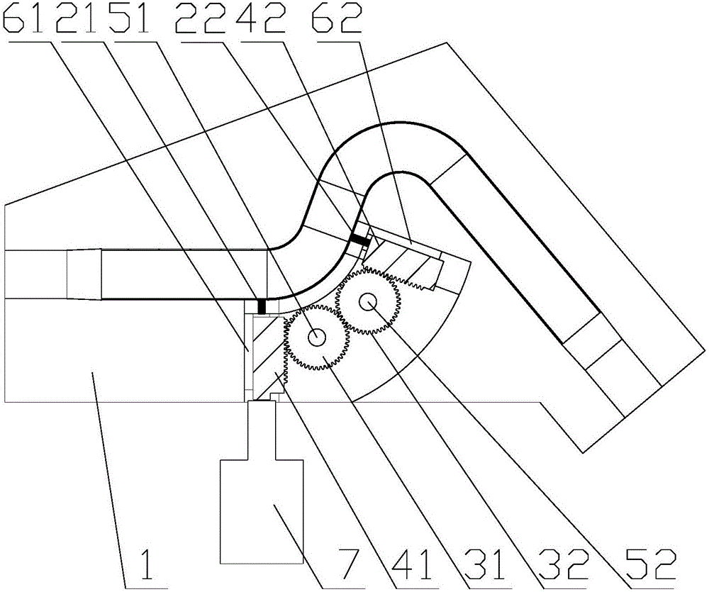
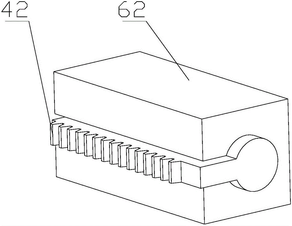
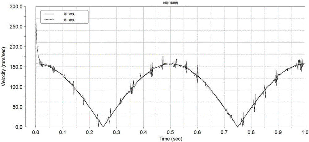
[0023] Such as Figure 1-4 as shown, figure 1 It is a structural schematic diagram of a synchronous punching device in an internal high pressure forming die proposed by the present invention, figure 2 It is a structural schematic diagram of the cooperation between the insert and the rack of a synchronous punching device in an internal high pressure forming die proposed by the present invention, image 3 for figure 1 The speed curves calculated by the simulation calculation of the first punch and the second punch, Figure 4 for figure 1 Displacement curves obtained from simulation calculations of the first punch and the second punch.

[0024] refer to figure 1 and 2 , a synchronous punching device in an internal high pressure forming mold proposed by the present invention, comprising: a mold assembly 1, a punching assembly, a liquid inlet mechanism, and a driving mechanism 7;

[0025] The mold assembly 1 has a mold cavity for accommodating pipe fittings to be processed,...


PUM


Abstract

The invention discloses a synchronous punching device in an internal high-pressure forming mold. After a pipe fitting to be molded is molded through the internal high-pressure forming mold, a pipe wall in a mold cavity is synchronously punched through a first punch and a second punch; high-pressure liquid in the pipe fitting is used for supporting to guarantee the punching effect; further, the first punch and the second punch are in engaged transmission through gears; on the one hand, the gear transmission guarantees the speed and the displacement transmission synchronism, so that the transmission reliability and the machining precision are improved; and on the other hand, because of angle flexibility of gear engagement, different positions on different planes can be synchronously punched, and the use flexibility is excellent and not limited by the use environment.

Description

technical field [0001] The invention relates to the technical field of pipe fitting processing, in particular to a synchronous punching device in an internal high pressure forming die. Background technique [0002] With the development of automobile lightweight, more and more internal high pressure forming products are used in automobile chassis, body and other structures. Under the action of pressure, by controlling the internal pressure and material flow of the tube blank, the tube blank is expanded radially outward to produce plastic deformation to form a hollow structural part. Many internal high pressure forming products need to process multiple holes for assembly and positioning. The traditional process generally uses drilling and milling, but the drilling accuracy is low and the milling efficiency is low. We are eager for a process with higher forming precision and higher processing efficiency, so the punching hole in the internal high pressure forming die has been w...

Claims


Application Information

Patent Timeline
Patent Type & Authority Applications(China)
IPC IPC(8): B21D53/88B21D35/00B21D28/34B21D26/047
CPCB21D26/047B21D28/34B21D35/001B21D53/88
Inventor 徐炎郑玉磊陈旭琳邓小波杨杰刘兵罗强丰
Owner BAOLONG ANHUI AUTO PARTS
Learn More