
Device for aligning strain clamp and splicing sleeve

A technology of strain clamps and connecting pipes, which is applied in the maintenance and connection of line connectors, overhead lines/cable equipment, etc., and can solve the problems of ineffective straightening, bending of the connecting part of strain clamps, and low straightening efficiency and other problems to achieve the effect of preventing scratches on the transmission lines, avoiding damage, and achieving obvious straightening effects

Inactive Publication Date: 2017-05-31
SHANDONG ELECTRIC POWER TRANSMISSION & SUBSTATION ENG CO
View PDF9 Cites 1 Cited by
  • Summary
  • Abstract
  • Description
  • Claims
  • Application Information

AI Technical Summary

Problems solved by technology

[0002] Both the tension clamp and the splicing pipe have the function of connection in the construction of the transmission line. The tension clamp includes a straight connection part. During the wiring process, the staff use hydraulic or pneumatic devices to move the wires It is crimped on the connection part of the tension clamp, and the connection part of the tension clamp will be slightly deformed during the process of being crimped, which will cause the connection part of the tension clamp to bend
[0003] The splicing tube is another commonly used wire splicing device in the construction of transmission lines. When using the splicing tube for wiring, the staff first place the end of the wire inside the splicing tube, and then use hydraulic pliers and other devices to squeeze the splicing tube. , so that the wire is crimped into the connecting tube, and the hydraulic tube will be slightly bent during the wiring process, which will lead to the problem of bending the line at the position of the wiring tube
[0004] In the prior art, workers use tools to tap the strain clamp or the connecting pipe to carry out the straightening work, which not only has the problem of low straightening efficiency but not obvious straightening effect, but also causes damage to the transmission line

Method used


Image

  • Device for aligning strain clamp and splicing sleeve
  • Device for aligning strain clamp and splicing sleeve
  • Device for aligning strain clamp and splicing sleeve

Examples


Embodiment Construction

[0027] In order to make the purpose, technical solutions and advantages of the embodiments of the present invention clearer, the technical solutions in the embodiments of the present invention will be clearly and completely described below in conjunction with the drawings in the embodiments of the present invention. Obviously, the described embodiments It is a part of embodiments of the present invention, but not all embodiments. Based on the embodiments of the present invention, all other embodiments obtained by persons of ordinary skill in the art without making creative efforts belong to the protection scope of the present invention.

[0028] In describing the present invention, the terms "upper", "lower", "left", "right", "front" and "rear" are based on figure 1 with figure 2 The orientations or positional relationships shown are only for the convenience of describing the present invention and simplifying the description, and do not indicate or imply that the referred de...


PUM


Abstract

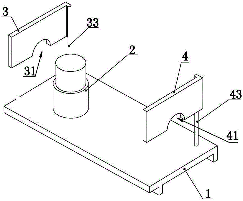
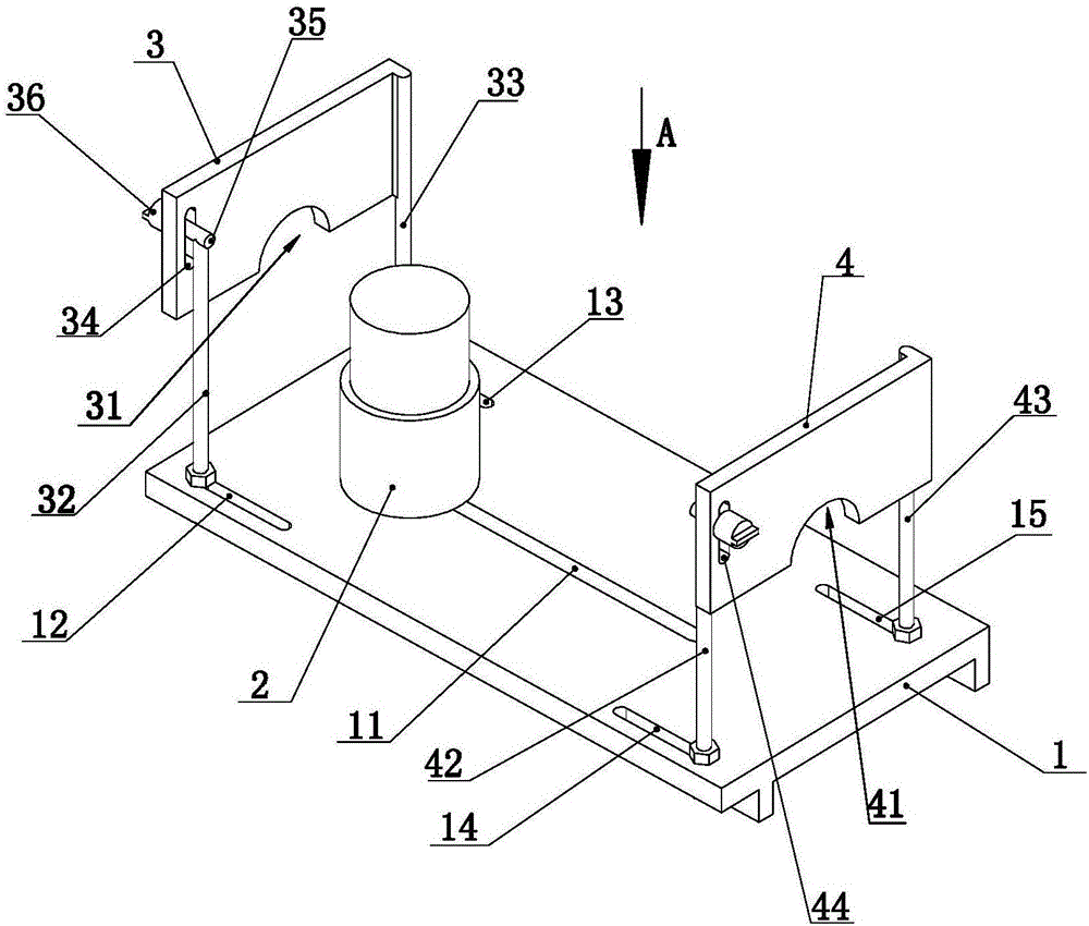
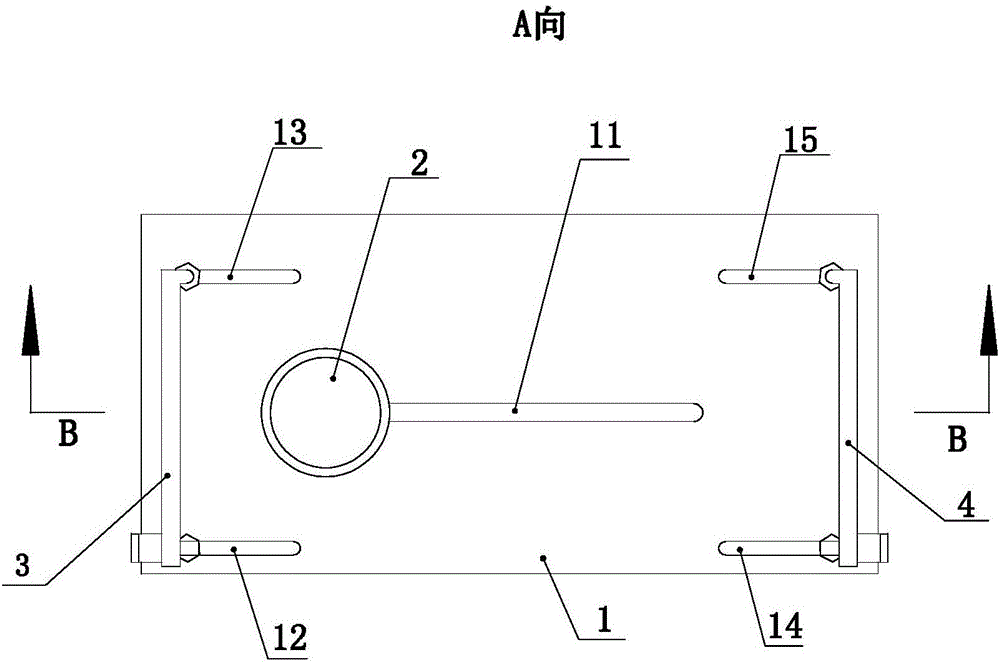
The invention relates to a device for aligning a strain clamp and a splicing sleeve. The device is used for rapidly aligning a connecting part of the strain clamp or the splicing sleeve. According to the technical scheme, the device for aligning the strain clamp and the splicing sleeve comprises a machine base, a hydraulic device and at least two adjusting bases, a base of the hydraulic device is arranged on the machine base, a working shaft of the hydraulic device is vertically arranged, at least one adjusting base is located above the left portion of the hydraulic device, at least one adjusting base is arranged above the right portion of the hydraulic device, and the adjusting bases are connected with the base; and each adjusting base comprises a groove, and the opening direction of each groove is downward. The device has the beneficial effects that the strain clamp or the splicing sleeve can be rapidly adjusted with high quality.

Description

technical field [0001] The invention relates to the technical field of electric power construction, in particular to a device for straightening tension clamps and connecting pipes. Background technique [0002] Both the tension clamp and the splicing pipe have the function of connection in the construction of the transmission line. The tension clamp includes a straight connection part. During the wiring process, the staff use a hydraulic or pneumatic device to move the wire When it is crimped on the connection part of the tension clamp, the connection part of the tension clamp will be slightly deformed in the process of being crimped, thus causing the connection part of the tension clamp to bend. [0003] The splicing tube is another commonly used wire splicing device in the construction process of transmission lines. When using the splicing tube for wiring, the staff first place the end of the wire inside the splicing tube, and then use hydraulic pliers and other devices to...

Claims


Application Information

Patent Timeline
IPC IPC(8): B21D3/10H02G1/02H01R43/00
CPCB21D3/10H01R43/002H02G1/02
Inventor 杨文柱傅淑昆王庆强陈冠初付淑贵张爱平李家成吕宁华烨曹传文韩涛张召刚陈志远高陈
Owner SHANDONG ELECTRIC POWER TRANSMISSION & SUBSTATION ENG CO
Learn More