Disc brake, brake caliper, and brake rotary lever

一种盘式制动器、转动杆的技术,应用在制动器类型、制动器的部件、轴向上制动器等方向,达到节省结构空间、减少密封面、大应用范围的效果

Active Publication Date: 2017-05-24
KNORR BREMSE SYST FUER NUTZFAHRZEUGE GMBH
View PDF9 Cites 11 Cited by
  • Summary
  • Abstract
  • Description
  • Claims
  • Application Information

AI Technical Summary

Problems solved by technology

This is seen as a disadvantage due to the number of parts and the necessary sealing surfaces

Method used


Image

  • Disc brake, brake caliper, and brake rotary lever
  • Disc brake, brake caliper, and brake rotary lever
  • Disc brake, brake caliper, and brake rotary lever

Examples


Embodiment Construction

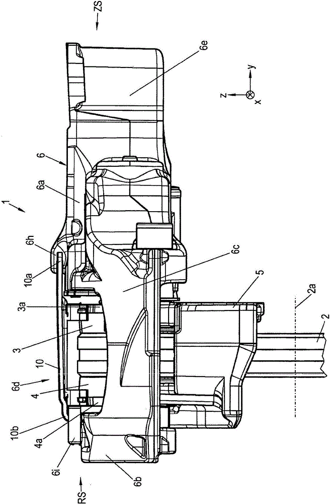
[0047] The coordinates x, y, z in the figures are used to simplify the orientation.

[0048] The contact side of the disc brake 1 is identified with the reference sign ZS, and the rear side of the disc brake 1 is designated with the reference sign RS.

[0049] figure 1 A schematic top view of an exemplary embodiment of a disk brake 1 according to the invention is shown. exist figure 2 shown in the figure 1 A schematic side view of a disc brake 1 according to the invention. image 3 show the basis figure 1 A schematic sectional view of a disc brake 1 according to the invention in the x-y plane.

[0050] Disk brake 1 has a brake disk 2 with a brake disk axis 2a. The brake disk 2 lies in the x-z plane, wherein the brake disk axis 2a extends in the y direction. A pressure-side brake lining 3 with a brake lining carrier 3 a is arranged on the pressure-side side of the brake disk 2 . A further rear brake lining 4 with a brake lining carrier 4 a is arranged on the rear side ...


PUM


Abstract

The invention relates to a disc brake (1), preferably a compressed air-actuated disc brake, in particular for a motor vehicle, having a brake application mechanism with a brake rotary lever (11), at least one spindle unit, each of which comprises a threaded rod screwed into a bridge, and a brake caliper (6), in particular a sliding caliper, which preferably covers an edge region of a brake disc (2) in the manner of a frame, said brake caliper (6) comprising a brake application portion (6a) and a caliper back (6b) which are connected together via tie bars. The brake application mechanism with the brake rotary lever (11) is received on an application face (ZS) of the brake disc (2) in the brake application portion (6a) of the brake caliper (6), and the brake application portion (6a) of the brake caliper (6) receives a first region, in which the application mechanism and a force transmission portion of the brake rotary lever (11) are arranged, a second region, which is formed as a lever housing (6e), and a lever portion of the brake rotary lever (11). A support wall (62) with a bearing portion (66), which forms a pivot bearing with a brake rotary lever axis that runs parallel to the brake disc (2), for the brake rotary lever (11) is arranged between the first region and the second region.

Description

technical field [0001] The invention relates to a disc brake according to the preamble of claim 1 . The invention also relates to a brake caliper and a brake turning lever. Background technique [0002] Disc brakes are preferred in the passenger car and commercial vehicle sector. In a typical design of a disc brake, the disc brake consists of a brake caliper with an inner mechanism, which usually consists of two brake linings and a brake disc. The force is introduced via a force source, for example via a pneumatically actuated cylinder by means of a piston rod, to an internal mechanism, also called a pressing mechanism, amplified by an eccentric mechanism and as a pressing force via a threaded tube (the threaded tube is also called a threaded cylinder) , screw, threaded rod, pressure rod, etc.) are transmitted to the brake lining and brake disc by means of a pusher, wherein the wear of the brake disc and brake lining is compensated by the threaded rod. [0003] The pressi...

Claims


Application Information

Patent Timeline
Patent Type & Authority Applications(China)
IPC IPC(8): F16D65/56F16D65/18F16D65/00F16D55/226
CPCF16D55/226F16D65/0068F16D65/18F16D65/183F16D65/568F16D2121/08F16D2121/14F16D2125/26F16D2125/32F16D2125/36F16D2125/64F16D65/0075F16D2121/02F16D2125/28
Inventor M·克林格纳R·韦伯P·亚当克齐克C·舒弗勒
Owner KNORR BREMSE SYST FUER NUTZFAHRZEUGE GMBH
Why Eureka
Try Eureka