
Driving method for display panel, time sequence controller and liquid crystal display

A timing controller and display panel technology, which is applied to static indicators, cathode ray tube indicators, instruments, etc., can solve the problems of high power consumption of source drivers, increased heat generation, and affecting product display quality, etc.

Inactive Publication Date: 2017-05-24
SHENZHEN CHINA STAR OPTOELECTRONICS TECH CO LTD
View PDF5 Cites 19 Cited by
  • Summary
  • Abstract
  • Description
  • Claims
  • Application Information

AI Technical Summary

Problems solved by technology

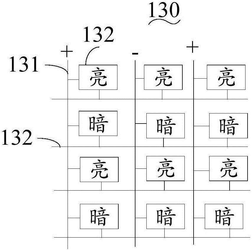
[0003] However, if the liquid crystal display needs to display a heavy-duty picture, that is, the power consumption of the source driver is too large when driving the heavy-duty picture, at this time, the output power consumption required by the source driver to form and maintain the driving voltage becomes larger At the same time, according to the driving mode of general liquid crystal display, the switching frequency of the high and low voltage changes of the data line is relatively fast, resulting in greater heat generation
If the heat dissipation measures are not good, the temperature will rise slowly, which will affect the display quality of the product

Method used


Image

  • Driving method for display panel, time sequence controller and liquid crystal display
  • Driving method for display panel, time sequence controller and liquid crystal display
  • Driving method for display panel, time sequence controller and liquid crystal display

Examples


Embodiment Construction

[0028] In the following description, for purposes of illustration rather than limitation, specific details, such as specific system architectures, interfaces, and techniques, are set forth in order to provide a thorough understanding of the present invention. It will be apparent, however, to one skilled in the art that the present invention may be practiced in other embodiments without these specific details. In other instances, detailed descriptions of well-known devices, circuits, and methods are omitted so as not to obscure the description of the present invention with unnecessary detail.

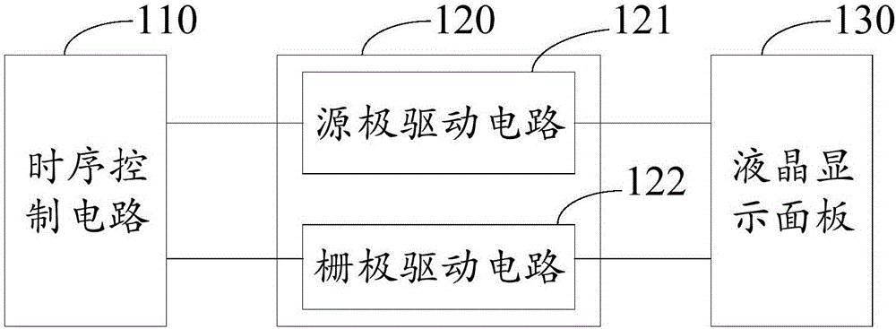
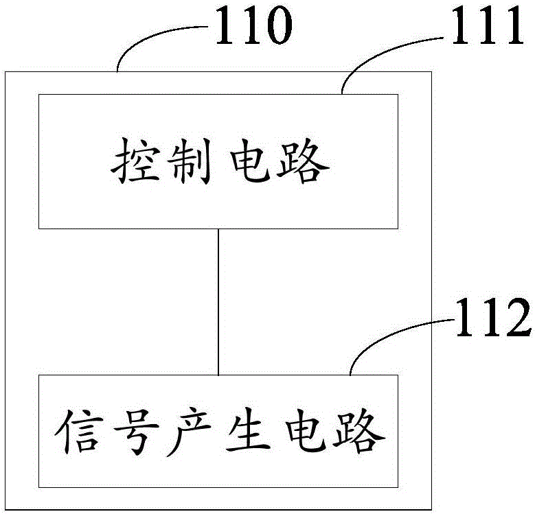
[0029] see figure 1 and figure 2 , figure 1 It is a structural schematic diagram of an embodiment of the liquid crystal display of the present invention, figure 2 It is a structural schematic diagram of an implementation circuit of the timing controller. The liquid crystal display is specifically a TFT liquid crystal display. In this embodiment, the liquid crystal display includes...


PUM


Abstract

The invention provides a driving method for a display panel, a time sequence controller and a liquid crystal display. The method comprises the steps of: when detecting a picture frame to be displayed is a reloaded picture, switching the working frequency from a first frequency to a second frequency by the time sequence controller; and outputting a time sequence control signal to a source driver by using the second frequency, so that the source driver outputs a driving signal with lower frequency to drive displaying of the reloaded picture, wherein the first frequency is higher than the second frequency. The driving method can avoid too high output power consumption of the source driver when the reloaded picture is displayed and avoid temperature rise to influence the display quality.

Description

technical field [0001] The invention relates to the field of display technology, in particular to a driving method of a display panel, a timing controller and a liquid crystal display. Background technique [0002] Currently, the most commonly used liquid crystal display is a thin film transistor (Thin Film Transistor, TFT) liquid crystal display. The TFT liquid crystal display adopts a source driver (Source Driver) to provide a driving voltage corresponding to an image to be displayed to the data line, so as to drive the display panel to display images. [0003] However, if the liquid crystal display needs to display a heavy-duty picture, that is, the power consumption of the source driver is too large when driving the heavy-duty picture, at this time, the output power consumption required by the source driver to form and maintain the driving voltage becomes larger , At the same time, according to the driving mode of the general liquid crystal display, the switching freque...

Claims


Application Information

Patent Timeline
IPC IPC(8): G09G3/36
CPCG09G3/3685G09G3/3674G09G5/18G09G2310/0278G09G2310/08G09G2330/023G09G2360/121G09G3/3677G09G3/3688G09G2320/041G09G2330/021
Inventor 吴宇王磊
Owner SHENZHEN CHINA STAR OPTOELECTRONICS TECH CO LTD
Learn More