A method for distinguishing upper and lower walls of faults in oilfield development zones

A technology for development zones and faults, applied in seismic signal processing and other directions, can solve the problems of uncertainty of seismic attributes, difficulty in distinguishing, and inability to intuitively distinguish fault breakpoints, so as to ensure the accuracy of judgment and reduce the complexity of judgment.

Active Publication Date: 2020-04-07
CHINA PETROLEUM & CHEM CORP +1
View PDF3 Cites 0 Cited by
  • Summary
  • Abstract
  • Description
  • Claims
  • Application Information

AI Technical Summary

Problems solved by technology

[0002] Distinguishing the upper and lower walls of a fault is a very important link to confirm the structure. The data used by seismic data interpreters to distinguish fault breakpoints mainly come from seismic data volumes and drilling layer data. The drilling layer data is relatively simple ASCII data, which cannot be intuitively To identify fault breakpoints, the existing technology to identify the hanging wall and footwall of geological faults relies more on seismic data, and it is necessary to accurately describe the breakpoints based on data with higher seismic resolution
Current technologies rely more on seismic attributes, such as coherence technology, ant body technology, variance body technology, dip angle analysis technology, and 3D visualization to assist fault identification, but complex fault zones are often areas with poor seismic imaging, which gives Seismic attribute extraction brings uncertainty and also restricts the correctness of fault identification
In particular, the upper and lower walls of reverse faults are often difficult to distinguish due to the repetition of strata and the poor effect of seismic imaging.

Method used


Image

  • A method for distinguishing upper and lower walls of faults in oilfield development zones
  • A method for distinguishing upper and lower walls of faults in oilfield development zones
  • A method for distinguishing upper and lower walls of faults in oilfield development zones

Examples


Embodiment Construction

[0010] Preferred embodiments of the present disclosure will be described in more detail below with reference to the accompanying drawings. Although preferred embodiments of the present disclosure are shown in the drawings, it should be understood that the present disclosure may be embodied in various forms and should not be limited to the embodiments set forth herein. Rather, these embodiments are provided so that this disclosure will be thorough and complete, and will fully convey the scope of the disclosure to those skilled in the art.

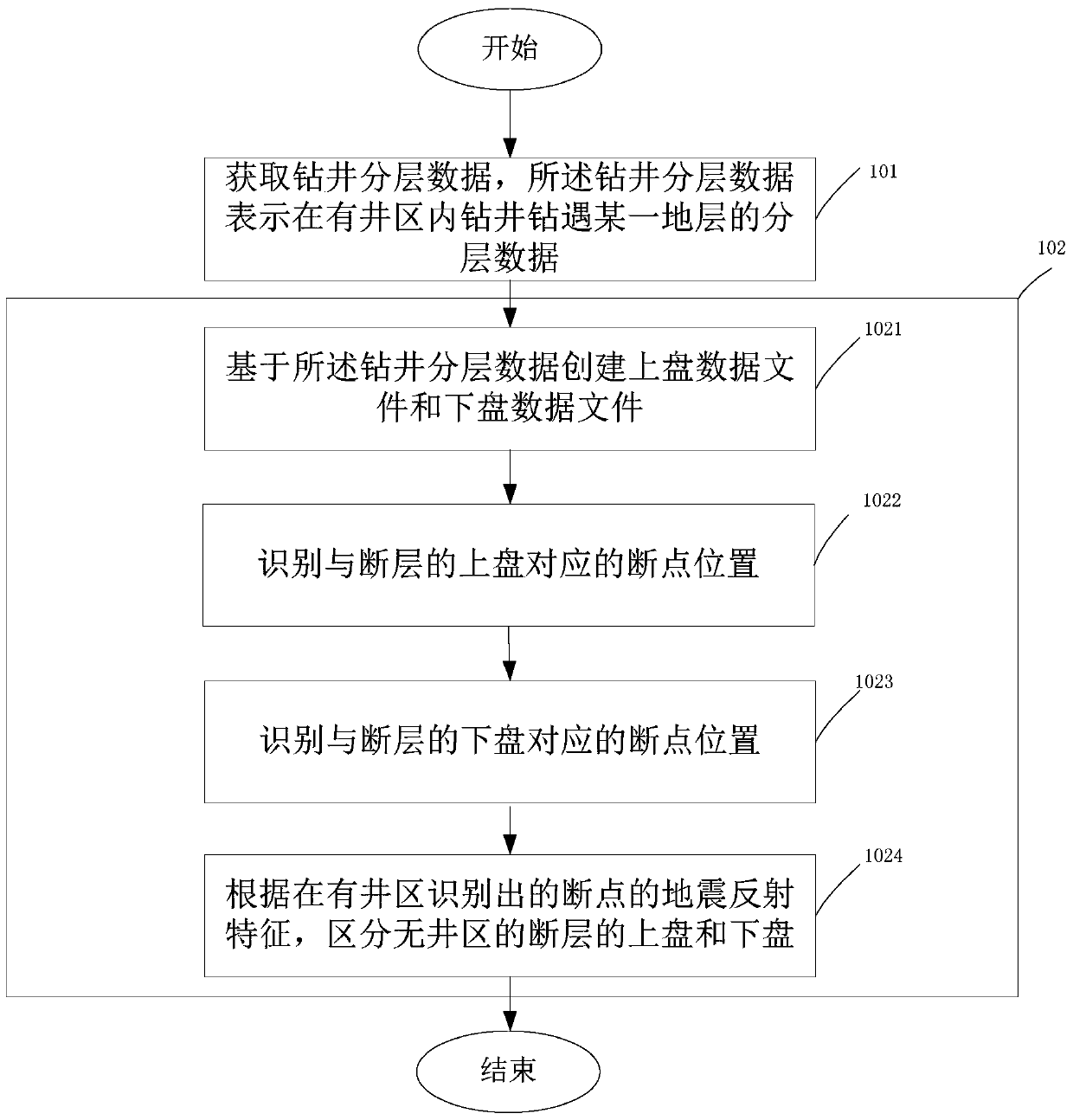
[0011] figure 1 A method for distinguishing the upper and lower walls of a fault in an oilfield development area according to an embodiment of the present invention is shown, the method includes:

[0012] Step 101, obtaining drilling stratification data, the drilling stratification data represents the stratification data of a certain stratum encountered by drilling in the well area, wherein the stratum is cut by a fault;

[0013] Step 102,...


PUM


Abstract

The invention provides a method for distinguishing a hanging wall and a footwall of a fault in an oilfield development zone. The method comprises a step of obtaining drilling well hierarchical data, a step of creating a hanging wall data file and a footwall data file based on the drilling well hierarchical data in the condition that the fault is a reverse fault, wherein the hanging wall data file comprises hierarchical data of only drilling a formation for one time and hierarchical data with a smaller depth in the hierarchical data of drilling the formation for two times, and the footwall data file comprises hierarchical data of only drilling a formation for one time and hierarchical data with a larger depth in the hierarchical data of drilling the formation for two times, a step of projecting the hierarchical data in the hanging wall data file into a seismic data interpretation system, and identifying the fault position corresponding to the hanging wall of the fault, a step of projecting the hierarchical data in the footwall data file into the seismic data interpretation system, and identifying the fault position corresponding to the footwall of the fault, and a step of distinguishing the hanging wall and footwall of the fault of a no-well zone according to the seismic reflection characteristic of a breakpoint identified in a well area.

Description

technical field [0001] The invention relates to the field of seismic data interpretation, more specifically, to a method for distinguishing upper and lower walls of faults in oil field development zones. Background technique [0002] Distinguishing the upper and lower walls of a fault is a very important link to confirm the structure. The data used by seismic data interpreters to distinguish fault breakpoints mainly come from seismic data volumes and drilling layer data. The drilling layer data is relatively simple ASCII data, which cannot be intuitively To identify fault breakpoints, the existing technology to identify the hanging wall and footwall of geological faults relies more on seismic data, and it is necessary to accurately characterize the breakpoints based on data with higher seismic resolution. Current technologies rely more on seismic attributes, such as coherence technology, ant body technology, variance body technology, dip angle analysis technology, and 3D vis...

Claims


Application Information

Patent Timeline
Patent Type & Authority Patents(China)
IPC IPC(8): G01V1/30
Inventor 袁红军王劲松张艳芳李军
Owner CHINA PETROLEUM & CHEM CORP
Why Eureka
Try Eureka