Line fault indicator

A line fault and indicator technology, applied in the fault location and other directions, can solve the problems of safety hazards, spontaneous combustion, electromagnet heating, etc., and achieve the effect of improving safety

Inactive Publication Date: 2017-05-24
TIANJIN SAISI TECH DEV
View PDF0 Cites 2 Cited by
  • Summary
  • Abstract
  • Description
  • Claims
  • Application Information

AI Technical Summary

Problems solved by technology

[0002] The most common faults in high-voltage transmission lines are single-phase ground faults and phase-to-phase short-circuit faults. When a high-voltage transmission line fails, if there is no online detection device, the only way to find the faulty section by segmental closing and blindly patrol the line Outdated practices will cause a great loss of human and financial resources
However, the fault indicator used in the prior art uses an electromagnet to drive the indicating mechanism to make an indicating action when a line fault is detected. However, the electromagnet will generate heat or even spontaneously ignite when it is powered on for a long time, which poses a great safety hazard.

Method used


Image

  • Line fault indicator
  • Line fault indicator
  • Line fault indicator

Examples


Embodiment Construction

[0021] It should be noted that, in the case of no conflict, the embodiments of the present invention and the features in the embodiments can be combined with each other.

[0022] The present invention will be described in detail below with reference to the accompanying drawings and examples.

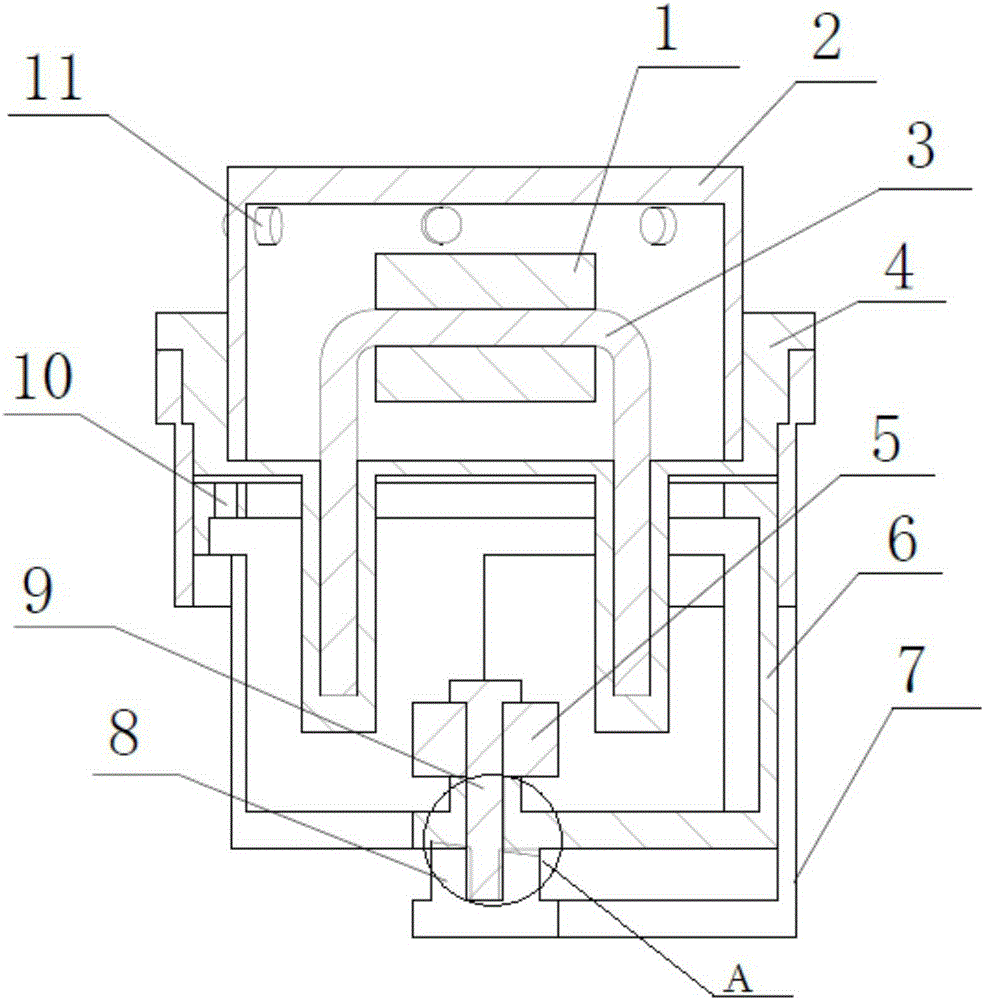
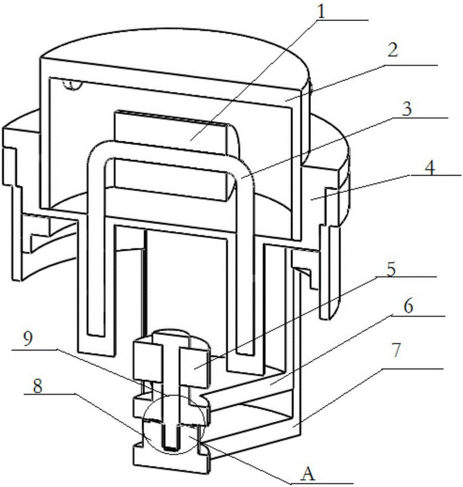
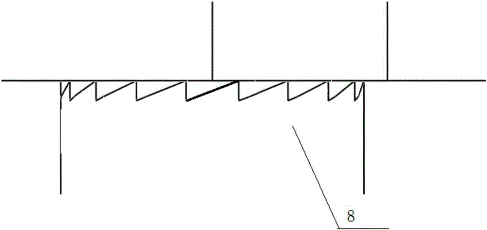
[0023] A line fault indicator, comprising a casing 7, an iron core 3, a coil 1 and a ring magnet 5, characterized in that: the casing 7 is a hollow cylinder, the casing 7 is equipped with a rotating body 6, and the rotating body 6 There is a ring magnet 5 inside, and the above-mentioned casing 7, rotating body 6, and ring magnet 5 are all concentric and connected together by pins 9. The boss at the center of the bottom of the casing 7 and the lower surface of the center of the rotating body 6 are distributed with mutually engaging There is a tooth-shaped protrusion 8 on the shell 7, and there is a connecting plate 4 on the shell 7. The connecting plate 4 has two symmetrical hollow groove...


PUM


Abstract

The invention provides a line fault indicator which comprises a shell, an iron core, a coil and an annular magnet. The shell is a hollow cylinder. A rotating body is installed in the shell and is internally provided with an annular magnet. The above shell, the rotating body and the annular magnet are concentric and are connected together by a pin. Tooth-shaped projections in mutual engagement are distributed at the boss of the bottom center of the shell and the lower surface of the center of the rotating body. The shell is connected to a connection plate which has two downward projecting hollow grooves. Two ends of the iron core are inserted into the hollow grooves. Coils are wound around iron cores. The connection plate is connected to an upper cover. The line fault indicator can receive the pulse signal emitted by a control circuit when a line is failed, a visual window is turned out of the rotating shaft, and the patrol personnel are reminded of a fault position. Compared with the prior art, a fault reminding state can be maintained through the energization of the electromagnet for one time, the continuous energization is not needed, and the safety is improved.

Description

technical field [0001] The invention belongs to the field of detecting line faults, in particular to a line fault indicator. Background technique [0002] The most common faults in high-voltage transmission lines are single-phase ground faults and phase-to-phase short-circuit faults. When a high-voltage transmission line fails, if there is no online detection device, the only way to find the faulty section by segmental closing and blindly patrol the line Backward practices will cause a great loss of human and financial resources. The fault indicator used in the prior art uses an electromagnet to drive the indicating mechanism to make an indicating action when a line fault is detected. However, the electromagnet will generate heat or even spontaneously ignite when it is powered on for a long time, which poses a great safety hazard. Contents of the invention [0003] In view of this, the present invention aims to provide a line fault indicator, which prompts line inspectors...

Claims


Application Information

Patent Timeline
Patent Type & Authority Applications(China)
IPC IPC(8): G01R31/08
Inventor 曲泰洲曲仕松
Owner TIANJIN SAISI TECH DEV
Why Eureka
Try Eureka