
Automatic single piece cutting machine

A technology of automatic cutting and single-chip microcomputer is applied in the field of fabric processing and forming, which can solve the problems of personal error, low work efficiency and large operation error.

Active Publication Date: 2017-05-24
SHAOXING BOYA FASHION CO LTD
View PDF8 Cites 1 Cited by
  • Summary
  • Abstract
  • Description
  • Claims
  • Application Information

AI Technical Summary

Problems solved by technology

In the conventional method, the garment pieces are usually cut by hand. This method not only has low work efficiency, but also has large operating errors, especially prone to personal errors caused by different operators, and ultimately affects the quality of the finished suit. Wearing comfort and shape crispness

Method used


Image

  • Automatic single piece cutting machine
  • Automatic single piece cutting machine
  • Automatic single piece cutting machine

Examples


Embodiment 1

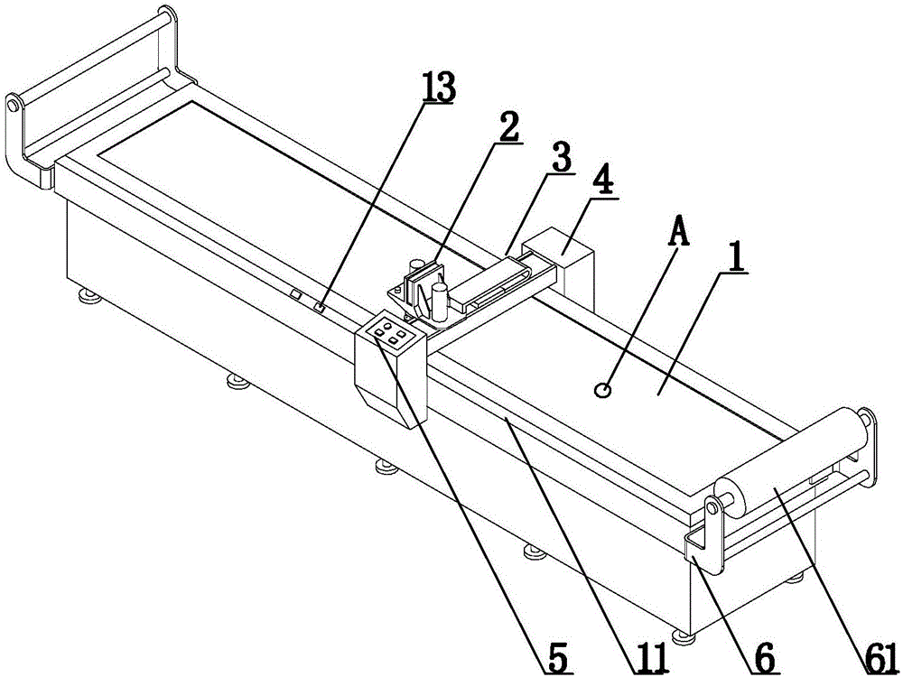
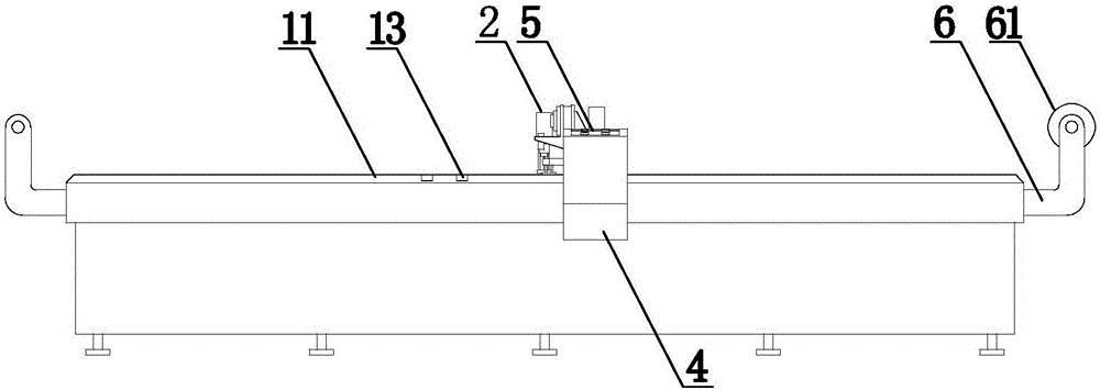
[0019] This embodiment cuts the single-chip microcomputer automatically, combines figure 1 , figure 2 , image 3 and Figure 4 , including workbench 1, cutting head 2, track 3, track frame 4 and controller 5, track frame 4 is a C-shaped structure, fastened on workbench 1, and track 3 passes through the track The frame 4 is erected on the workbench 1, the track frame 4 and the track 3 are respectively connected with the controller 5, and the controller 5 drives the track frame 4 to move back and forth along the workbench 1 (that is, to move along the length direction of the workbench 1), and the controller 5 The drive track 3 moves left and right on the track frame 4, the cutting head 2 is connected with the track 3, and moves with the movement of the track 3, and the movement of the track frame 4 and the track 3 jointly realizes the movement of the cutting head 2 position; the cutting head 2 Driven by the driving source to move up and down, the cutting head 2 realizes cutt...

Embodiment 2

[0023] The setting and working principle of this embodiment are the same as that of Embodiment 1, the difference is that: a side beam 11 is arranged on the periphery of the workbench 1, and the track frame 4 is erected on the side beam 11 in its length direction, and under the drive of the controller 5, Move back and forth along the side beam 11. The side beam 11 of the workbench 1 provides a point of force for the track frame 4, and fixes the moving track of the track frame 4, avoiding the dislocation caused by the excessive movement of the track frame 4, and effectively ensuring the movement accuracy.

Embodiment 3

[0025] The setting and working principle of this embodiment are the same as that of Embodiment 1, the difference is that: a side beam 11 is arranged on the periphery of the workbench 1, and the track frame 4 is erected on the side beam 11 in its length direction, and under the drive of the controller 5, Move back and forth along the side beam 11; the side beam 11 is provided with a return switch 13, the return switch 13 is connected with the controller 5, when the cutting is completed, start the return switch 13, the controller 5 drives the track frame 4 and the Track 3 and cutting head 2 reset, waiting for the next operation.


PUM

PropertyMeasurementUnit
Widthaaaaaaaaaa

Abstract

The invention relates to an automatic single piece cutting machine, and belongs to the field of textile processing and forming technologies. The automatic single piece cutting machine comprises a worktable, a cutting head and a track. The track is erected on the worktable by a track frame, the track frame can move front and back along the worktable under the control of a controller, and the cutting head is connected with the track and can be driven by the track to move left and right; the cutting head can be repositioned jointly under the effect of the track frame and the track; the cutting head can be driven by driving sources to move up and down, and cloth pieces can be cut by the cutting head in up-down, left-right and front-back movement procedures. The automatic single piece cutting machine has the advantages that the automatic single piece cutting machine can be applied to processing western-style clothing and garments, the cloth pieces can be integrally cut and can be automatically clipped, and the like.

Description

technical field [0001] The invention relates to an automatic cutting single-chip machine, which belongs to the technical field of fabric processing and molding. Background technique [0002] Suit is a kind of clothing that is more common in people's social process. Its straight and clear lines give the wearer a good professional image. In the process of suit processing, due to the characteristics of the fabric itself, the finished garment is usually composed of multiple garment parts, not only the body part, but also the shoulders, back, sleeves, collar and other parts need to be cut and spliced ​​to form a complete clothing. In the conventional method, the garment pieces are usually cut by hand. This method not only has low work efficiency, but also has large operating errors, especially prone to personal errors caused by different operators, and ultimately affects the quality of the finished suit. Wearing comfort and shape crispness. [0003] Based on this, this applica...

Claims


Application Information

Patent Timeline
IPC IPC(8): D06H7/00
CPCD06H7/00
Inventor 李雅建
Owner SHAOXING BOYA FASHION CO LTD
Learn More