
Filling and sealing machine for syringes

A filling, sealing and syringe technology, applied in the field of medical devices, can solve the problems of stabbing medical staff, cumbersome process steps, syringe damage, etc., achieving the effects of easy control, avoiding stabbing medical staff, and low cost

Active Publication Date: 2017-05-24
SHINVA MEDICAL INSTR CO LTD
View PDF8 Cites 13 Cited by
  • Summary
  • Abstract
  • Description
  • Claims
  • Application Information

AI Technical Summary

Problems solved by technology

[0004] During the operation of the traditional method, there is a risk of secondary infection; the process steps are relatively cumbersome; there is a risk of stabbing medical staff; there is a risk of wrongly mixing the drug solution; while the catheter flusher is pre-filled with locking solution in the syringe , and undergo terminal sterilization, which can effectively avoid the above risks
The transmission in the existing mode is driven by sprockets, synchronous pulleys, and gears, and it needs to be lubricated with lubricating oil, so there will be corresponding oil pollution; the existing equipment of the thrust assembly is realized by extrusion of silicone wheels and syringes, and this method will As a result, when the main disk rotates to transmit the syringe, the syringe will rotate relatively, so that the syringe will rub against the main disk made of nylon material, causing damage to the syringe; the transmission of the existing equipment is relatively complicated, and multiple servo motors are used, and the cost is high. In addition to the use of servo motors to control the filling plunger pump up and down, the rest are realized by ordinary three-phase asynchronous motors or cylinders, and the cost is relatively low

Method used


Image

  • Filling and sealing machine for syringes
  • Filling and sealing machine for syringes
  • Filling and sealing machine for syringes

Examples


Embodiment Construction

[0042] The core of the present invention is to provide a syringe filling and sealing machine, which can effectively reduce secondary pollution and improve the safety of transfusion.

[0043] The following will clearly and completely describe the technical solutions in the embodiments of the present invention with reference to the accompanying drawings in the embodiments of the present invention. Obviously, the described embodiments are only some, not all, embodiments of the present invention. Based on the embodiments of the present invention, all other embodiments obtained by persons of ordinary skill in the art without making creative efforts belong to the protection scope of the present invention.

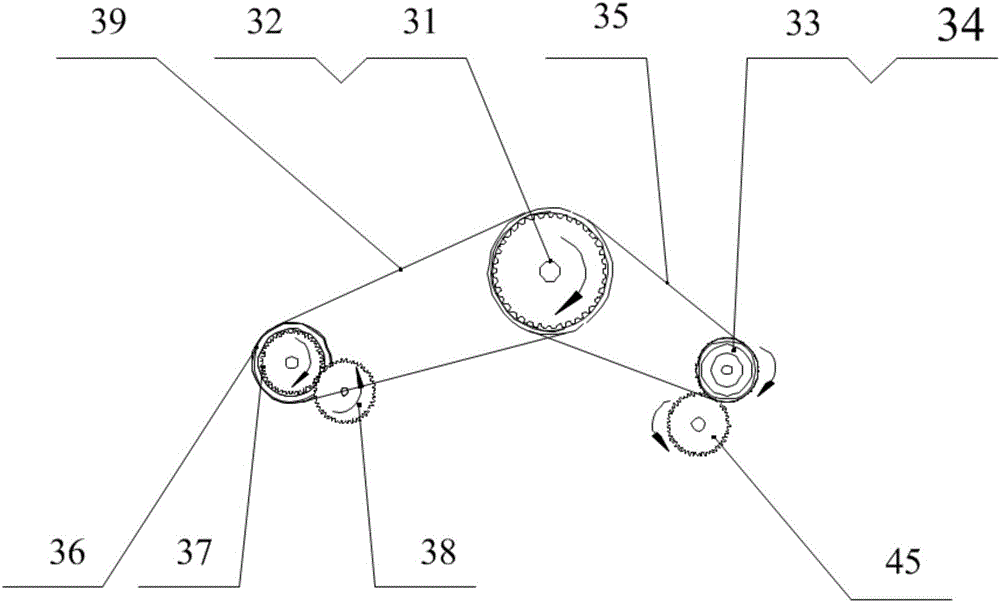
[0044] Please refer to Figure 1 to Figure 8 , figure 1 A schematic diagram of the overall layout of the syringe filling and sealing machine provided in a specific embodiment of the present invention; figure 2 for figure 1 Schematic diagram of the structure of the transmissio...


PUM


Abstract

The invention discloses a filling and sealing machine for syringes. The filling and sealing machine comprises a main disc capable of doing intermittent rotation motion, an upper syringe device, a downward pressing device, a filling device, a pre-screwing device, a cap screwing device and an output device, wherein the upper syringe device, the downward pressing device, the filling device, the pre-screwing device, the cap screwing device and the output device are sequentially distributed on the periphery of the main disc. A groove for containing the syringes is formed in the main disc. The syringes are transferred to the groove of the main disc through the upper syringe device and are moved to stations where corresponding devices are located along with rotation of the main disc. A filling pump assembly through which the syringe is filled with liquid is arranged on the filling device. The pre-screwing device is used for hanging a cone-head cap on the syringe filled with the liquid in advance. The cap screwing device is used for screwing up the cone-head cap hung on the syringe. The output device outputs the syringes obtained after filling and sealing are completed by outputting the rotary disc. By the adoption of the filling and sealing machine for the syringes, the secondary pollution is reduced effectively, and the transfusion safety is improved.

Description

technical field [0001] The invention relates to the technical field of medical devices, in particular to a syringe filling and sealing machine. Background technique [0002] With the widespread use of intravenous drip at present, indwelling needles are widely used because they do not need to be repeatedly punctured and will not cause skin pain and psychological panic to the human body. The intravenous indwelling needle is also called the venous trocar. The core components include a soft catheter or cannula that can be indwelled in the blood vessel, and a stainless steel puncture guide needle core. When in use, the catheter or cannula and the needle core are punctured into the blood vessel together. When the catheter or cannula has completely entered the blood vessel, the needle core is withdrawn, and only the soft catheter is left in the blood vessel for infusion therapy. [0003] Catheter flushers are used with indwelling needles. After the infusion is completed, the indw...

Claims


Application Information

Patent Timeline
Patent Type & Authority Applications(China)
IPC IPC(8): B65B43/50B65B3/12B65B7/28B65B65/02
CPCB65B3/12B65B7/2835B65B43/50B65B65/02
Inventor 薛德波冯国威孟凡一潘旭辉
Owner SHINVA MEDICAL INSTR CO LTD
Learn More