
Multi-cutter-head household garbage crushing structure

A domestic waste, multi-cutter technology

Inactive Publication Date: 2017-05-24
重庆市永铭再生资源回收有限公司
View PDF0 Cites 0 Cited by
  • Summary
  • Abstract
  • Description
  • Claims
  • Application Information

AI Technical Summary

Problems solved by technology

The existing garbage shredder lacks an effective cooling mechanism. During the crushing process, the cutter head rubs against the garbage a lot, and the heat generated is difficult to dissipate, resulting in overheating of the cutter head, which reduces the mechanical properties of the cutter head and greatly affects the crushing efficiency. Reduced cutter life

Method used


Image

  • Multi-cutter-head household garbage crushing structure
  • Multi-cutter-head household garbage crushing structure

Examples


Embodiment 1

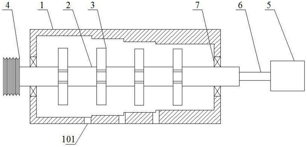
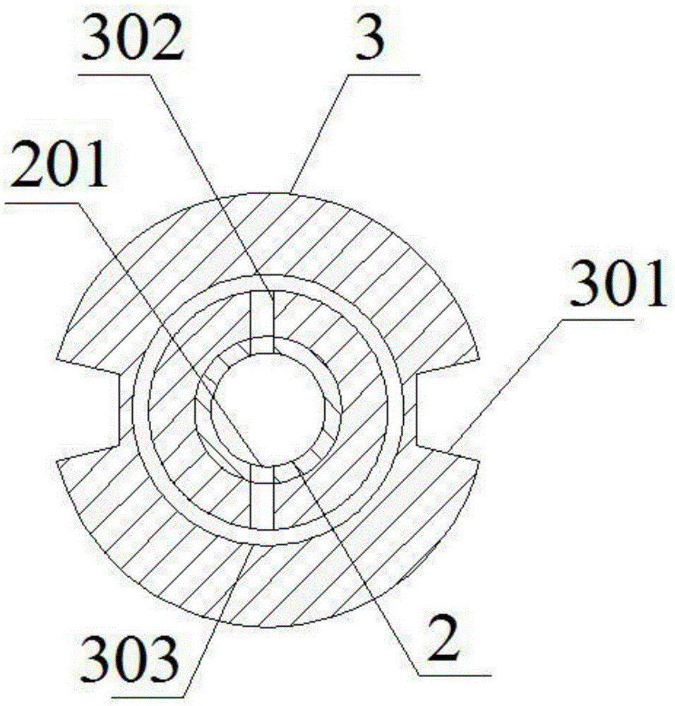
[0030] like figure 1 and figure 2 As shown, the multi-cutter domestic waste crushing structure includes a crushing chamber 1, a rotating shaft 2, a cutter head 3, a pulley 4, a water pump 5 and a connecting pipe 6; the rotating shaft 2 is arranged in the crushing chamber 1, and the rotating shaft 2 includes a first end and a second end. Two ends, the interior of the rotating shaft 2 is a hollow structure, the first end of the rotating shaft 2 is closed, and the second end of the rotating shaft 2 is open; The end runs through the wall of the crushing chamber 1, the inlet end of the connecting pipe 6 is connected to the outlet of the water pump 5, the outlet end of the connecting pipe 6 is inserted into the second end of the rotating shaft 2, the outlet end of the connecting pipe 6 is coaxial with the rotating shaft 2, and connected There is a gap between the outer surface of the tube 6 and the inner surface of the rotating shaft 2; a plurality of cutter heads 3 are located in...

Embodiment 2

[0035] like figure 1 As shown, on the basis of Embodiment 1, this embodiment also includes two support bearings 7, and the two support bearings 7 are respectively arranged at the first end and the second end of the rotating shaft 2 and pass through the cavity of the crushing chamber 1 wall.

Embodiment 3

[0037] like figure 1 As shown, this embodiment is based on Embodiment 1, and the bottom of the crushing chamber 1 is provided with a plurality of water seepage holes 101 .

[0038] Water seepage holes 101 are provided to facilitate the discharge of liquid in the garbage and reduce the load on the cutter head 3 .


PUM


Abstract

The invention discloses a multi-cutter-head household garbage crushing structure. The multi-cutter-head household garbage crushing structure comprises a crushing cavity, a rotating shaft, a plurality of cutter heads, a belt pulley, a water pump and a connecting tube, wherein the rotating shaft is arranged in the crushing cavity; the inside of the rotating shaft is of a hollow structure; an inlet end of the connecting tube is connected with an outlet of the water pump; an outlet end of the connecting tube is inserted in a second end of the rotating shaft; the cutter heads are positioned in the crushing cavity and are uniformly fixed on the rotating shaft; a straight hole is formed in the inner surface of each cutter head; a water outlet through hole which communicates with the straight holes is formed in an external circular surface of the rotating shaft; an annular hole which communicates with the bottom of the corresponding straight hole is further formed in each cutter head; each annular hole is coaxial with the corresponding cutter head; the crushing cavity comprises a plurality of secondary crushing cavities; the number of the secondary crushing cavities is the same as that of the cutter heads; each secondary crushing cavity corresponds to the corresponding cutter head; and the diameters of the secondary crushing cavities are successively reduced in the direction from the first end to the second end of the rotating shaft. By the annular holes, edges, which are rubbed intensely, of the cutter heads can be cooled, and therefore, the cooling performance is improved.

Description

technical field [0001] The invention relates to the field of recovery and treatment of renewable resources, in particular to a crushing device. Background technique [0002] With the development of the national economy and the improvement of people's living standards, the amount of domestic waste has also increased. As a result, enterprises dedicated to the recycling and reuse of domestic waste have emerged, and a set of treatment processes for the recycling and reuse of domestic waste have been developed. When processing domestic waste, first classify and collect domestic waste, then crush domestic waste, and finally reuse different types of waste particles. [0003] At present, garbage is mainly pulverized by garbage pulverizers. The garbage shredder mainly includes a rotating shaft and a cutter head, and the rotating shaft drives the cutter head to rotate, thereby crushing the garbage. The existing garbage shredder lacks an effective cooling mechanism. During the crush...

Claims


Application Information

Patent Timeline
Patent Type & Authority Applications(China)
IPC IPC(8): B02C18/14B02C18/16B02C18/18B02C18/24
CPCB02C18/145B02C18/16B02C18/182B02C18/24B02C2018/162B02C2201/06
Inventor 吴菊中
Owner 重庆市永铭再生资源回收有限公司
Learn More