
Air filter element cleaning device

A technology of air filter element and cleaning device, which is applied in gas treatment, smoke removal, transportation and packaging, etc., can solve the problems of complicated disassembly and assembly process of air filter element, affecting operation efficiency, increasing environmental protection pressure, etc., so as to improve the cleaning effect and improve the Cleaning efficiency, ensuring the effect of normal use

Active Publication Date: 2017-05-24
HMEI THREAD CO LTD OF YINBIN SICHUAN
View PDF18 Cites 6 Cited by
  • Summary
  • Abstract
  • Description
  • Claims
  • Application Information

AI Technical Summary

Problems solved by technology

[0007]1. The structure is quite complicated. The air filter element needs to be removed from the air compressor and placed on the rotating device to clean it. The air filter element is often disassembled and assembled. The process is complicated and time-consuming Laborious, affecting work efficiency;
[0008]2. Maintenance and cleaning personnel frequently come in and out of the air compressor to disassemble and install the air filter element, which poses a serious safety hazard;
[0009]3. The dust cleaned from the air filter cleaner is scattered in the air and cannot be treated, which seriously affects environmental sanitation and increases the pressure on environmental protection;
[0010]4. The cleaning effect is poor and the cleaning is not thorough

Method used


Image

  • Air filter element cleaning device
  • Air filter element cleaning device
  • Air filter element cleaning device

Examples


Embodiment 1

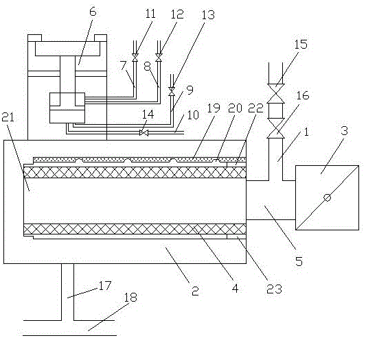
[0043] see figure 1 , an air filter element cleaning device, including a dust removal pipe 1, and also includes a drum cover 2, the dust removal pipe 1 is connected to the pipeline 5 between the intake butterfly valve 3 and the air filter element 4 of the main engine of the air compressor, The drum cover 2 is connected with a pneumatic control valve 6, and the pneumatic control valve 6 is connected with a first plunger inlet pipe 7, a first plunger exhaust pipe 8, a second plunger inlet pipe 9 and a second plunger inlet pipe. The plunger exhaust pipe 10, the first plunger intake pipe 7 is provided with a first intake switch valve 11, the first plunger exhaust pipe 8 is provided with a first exhaust switch valve 12, the second plunger intake pipe 9 is provided with a second intake switch valve 13, the second plunger exhaust pipe 10 is provided with a second exhaust switch valve 14, and the dust cleaning pipe 1 is provided with an intake valve 15 and a pressure reducing valve 16...

Embodiment 2

[0046] see figure 2 , an air filter element cleaning device, including a dust removal pipe 1, and also includes a drum cover 2, the dust removal pipe 1 is connected to the pipeline 5 between the intake butterfly valve 3 and the air filter element 4 of the main engine of the air compressor, The drum cover 2 is connected with a pneumatic control valve 6, and the pneumatic control valve 6 is connected with a first plunger inlet pipe 7, a first plunger exhaust pipe 8, a second plunger inlet pipe 9 and a second plunger inlet pipe. The plunger exhaust pipe 10, the first plunger intake pipe 7 is provided with a first intake switch valve 11, the first plunger exhaust pipe 8 is provided with a first exhaust switch valve 12, the second plunger intake pipe 9 is provided with a second intake switch valve 13, the second plunger exhaust pipe 10 is provided with a second exhaust switch valve 14, and the dust cleaning pipe 1 is provided with an intake valve 15 and a pressure reducing valve 1...

Embodiment 3

[0051] see image 3 , an air filter element cleaning device, including a dust removal pipe 1, and also includes a drum cover 2, the dust removal pipe 1 is connected to the pipeline 5 between the intake butterfly valve 3 and the air filter element 4 of the main engine of the air compressor, The drum cover 2 is connected with a pneumatic control valve 6, and the pneumatic control valve 6 is connected with a first plunger inlet pipe 7, a first plunger exhaust pipe 8, a second plunger inlet pipe 9 and a second plunger inlet pipe. The plunger exhaust pipe 10, the first plunger intake pipe 7 is provided with a first intake switch valve 11, the first plunger exhaust pipe 8 is provided with a first exhaust switch valve 12, the second plunger intake pipe 9 is provided with a second intake switch valve 13, the second plunger exhaust pipe 10 is provided with a second exhaust switch valve 14, and the dust cleaning pipe 1 is provided with an intake valve 15 and a pressure reducing valve 16...


PUM

PropertyMeasurementUnit
Depthaaaaaaaaaa

Abstract

The invention discloses an air filter element cleaning device, and belongs to the technical field of filter element cleaning equipment. The air filter element cleaning device comprises a dust cleaning tube as well as a bucket cover, wherein a pneumatic control valve is connected with the bucket cover; a first plunger air inlet tube, a first plunger air discharge tube, a second plunger air inlet tube and a second plunger air discharge tube are connected with the pneumatic control valve; a firs air inlet switch valve is arranged on the first plunger air inlet tube; a first air discharge switch valve is arranged on the first plunger air discharge tube; a second air inlet switch valve is arranged on the second plunger air inlet tube; a second air discharge switch valve is arranged on the second plunger air discharge tube; a dust discharge tube is arranged on the bucket cover; one end of the dust discharge tube is connected with the lower side wall of the bucket cover, and the other end of the dust discharge tube is connected with a condensed water tube of an air compressor; an activated carbon plate is adhered to the inner wall of the upper side wall of the bucket cover; and a plurality of semispherical grooves are formed in the activated carbon plate. By adopting the air filter element cleaning device, an air filter element can be cleaned without detaching down the air filter element, so that the working efficiency can be improved, and dust can be cleaned relatively thoroughly and comprehensively.

Description

technical field [0001] The invention relates to the technical field of filter element cleaning equipment, in particular to an air filter element cleaning device. Background technique [0002] The air filter of the air compressor is composed of an air filter assembly and a filter element, and the outside is connected to the intake valve of the air compressor through joints and threaded pipes to filter impurities such as dust and particles entering the air. Different air compressor models can choose the air filter to be installed according to the size of the air intake. [0003] Particulate pollutants suspended in the air are composed of solid or liquid particles. Atmospheric dust can be divided into narrow sense atmospheric dust and broad sense atmospheric dust: narrow sense atmospheric dust refers to solid particles in the atmosphere, that is, real dust; atmospheric dust includes both solid particles and polydisperse aerosols of liquid particles, which refers to Suspended ...

Claims


Application Information

Patent Timeline
IPC IPC(8): B01D46/00B01D47/02B01D46/48B08B15/04
CPCB01D46/00B01D46/48B01D47/02B08B15/04B01D2258/06B01D46/681
Inventor 万立新张创翁俊
Owner HMEI THREAD CO LTD OF YINBIN SICHUAN
Learn More