Phase-modulated standing wave mixing apparatus and methods

A technology of mixing devices and phase modulators, applied in chemical instruments and methods, mixers, measuring devices, etc., capable of solving complex and expensive system problems

Active Publication Date: 2017-05-17
SIEMENS HEALTHCARE DIAGNOSTICS INC
View PDF16 Cites 4 Cited by
  • Summary
  • Abstract
  • Description
  • Claims
  • Application Information

AI Technical Summary

Problems solved by technology

However, while such methods can result in adequate mi

Method used


Image

  • Phase-modulated standing wave mixing apparatus and methods
  • Phase-modulated standing wave mixing apparatus and methods
  • Phase-modulated standing wave mixing apparatus and methods

Examples


Embodiment Construction

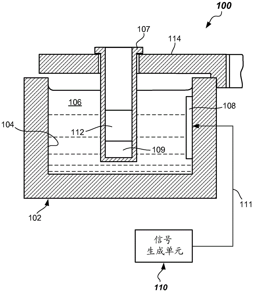
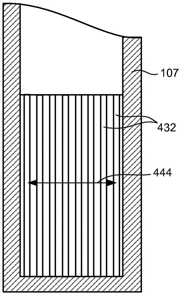
[0021] It is desirable to achieve improved mixing of components, particularly one or more reagents and a patient sample in a clinical analyte test or analysis, for at least the reasons described above. The inventors herein have discovered a simple yet effective way of generating a standing wave within a reaction vessel (e.g., a test tube) containing the components to be mixed, and then moving (e.g., oscillating) the standing wave back and forth within the reaction vessel so that Mix ingredients thoroughly.

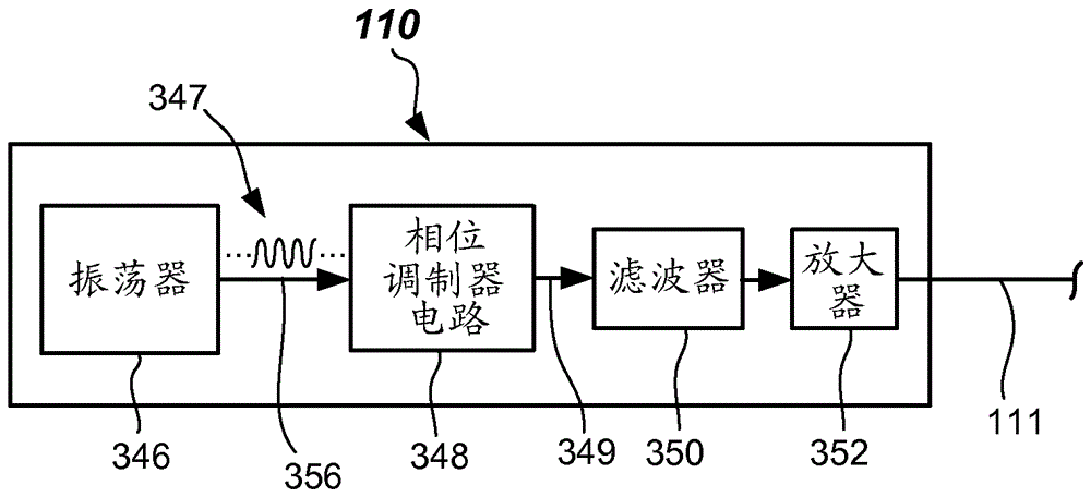
[0022] According to an embodiment of the invention, improved mixing is achieved by driving a high frequency transducer fluidly coupled to the reaction vessel (such as by coupling a liquid) to set up a standing wave (e.g., a vertically oriented standing wave) in the reaction vessel . The drive signal to the transducer is phase modulated to move the position of the standing wave laterally back and forth within the reaction vessel to achieve mixing.

[0023] will be referre...


PUM


Abstract

Disclosed are mixing apparatus adapted to provide mixing of components in an automated analyzer. The mixing apparatus includes a reservoir configured to contain a coupling liquid, a transducer configured to be driven at a frequency and communicate with the coupling liquid, and a signal generation unit configured to provide a phase modulatable drive signal to the transducer. In some embodiments, improved patient sample and reagent mixing may be provided. Systems and methods are provided, as are other aspects.

Description

[0001] related application [0002] This application claims priority to U.S. Provisional Application Serial No. 62 / 056,194, filed September 26, 2014, entitled "PHASE-MODULATED STANDING WAVE MIXING APPARATUS AND METHODS," the disclosure of which is hereby incorporated by reference in its entirety Incorporated into this article. technical field [0003] The present invention generally relates to methods and systems adapted to mix various components, such as liquids or combinations of liquids and solids. Background technique [0004] In the implementation of an automated clinical chemistry test method, a liquid sample (eg, a patient sample) is combined with reagents and possibly other process fluids. Conventionally, a liquid sample (e.g., patient sample), one or more process fluids (e.g., purified water), and reagents are transferred to a reaction vessel within an automated clinical analyzer, such as by using a probe (otherwise known as a pipette). (e.g., test tubes) for aspi...

Claims


Application Information

Patent Timeline
IPC IPC(8): G01N15/14G01N1/40
CPCG01N35/025G01N35/026G01N35/10G01N2035/00554B01F2215/0454B01F31/87
Inventor S.克鲁夫卡A.哈达德J.泰勒
Owner SIEMENS HEALTHCARE DIAGNOSTICS INC
Why Eureka
Try Eureka