
A large beam diameter ion source and screen grid

An ion source and ion beam technology, applied in the field of ion beams, can solve the problem of low beam density uniformity, and achieve the effects of improving beam uniformity, strong beam stability, and excellent flatness parameters.

Active Publication Date: 2019-05-07
北京埃德万斯离子束技术研究所股份有限公司
View PDF4 Cites 0 Cited by
  • Summary
  • Abstract
  • Description
  • Claims
  • Application Information

AI Technical Summary

Problems solved by technology

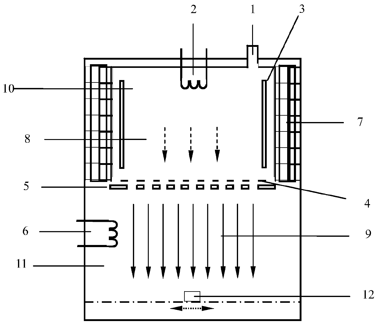
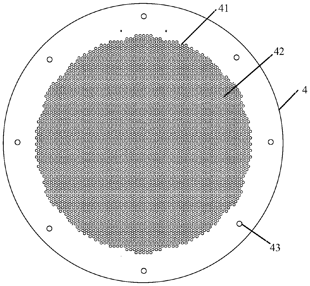
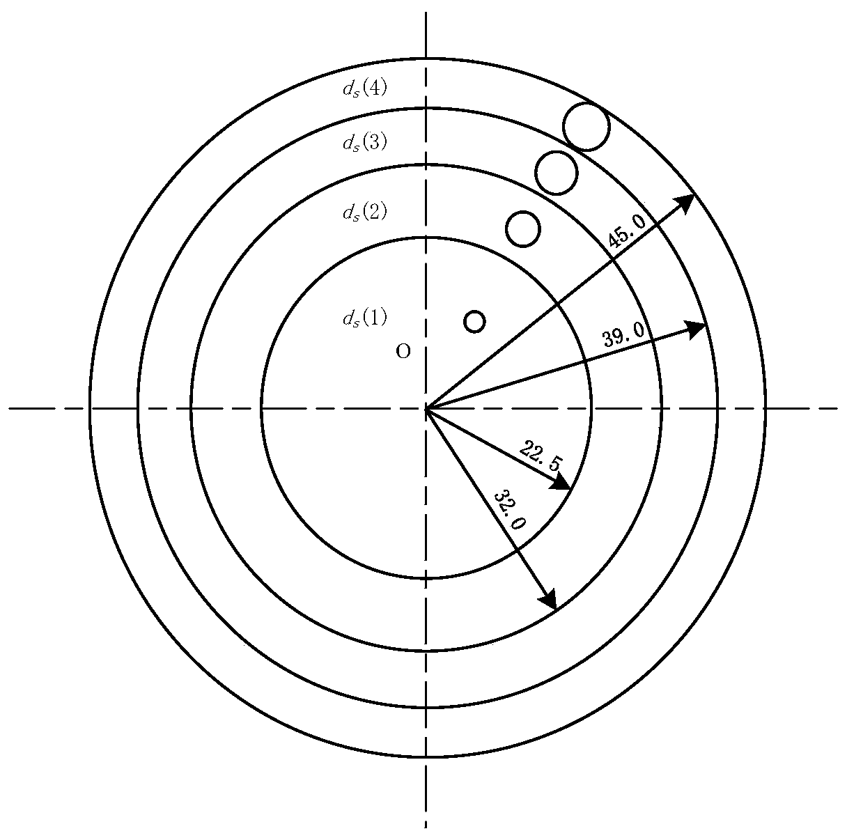
[0004] The technical problem to be solved by the present invention is to provide a large beam diameter ion source and the screen that adopts a variable aperture screen grid to improve the uniformity of the beam current density in view of the defect that the beam current density uniformity of the existing large beam diameter ion source is not high. grid

Method used


Image

  • A large beam diameter ion source and screen grid
  • A large beam diameter ion source and screen grid
  • A large beam diameter ion source and screen grid

Examples


Embodiment Construction

[0028] In order to make the object, technical solution and advantages of the present invention clearer, the present invention will be further described in detail below in conjunction with the accompanying drawings and embodiments.

[0029] Various structural diagrams, principle diagrams and effect diagrams according to the embodiments of the present disclosure are shown in the accompanying drawings. The figures are not drawn to scale, with certain details exaggerated and possibly omitted for clarity of presentation. The shapes of the various regions and layers shown in the figure, as well as their relative sizes and positional relationships are only exemplary, and may deviate due to manufacturing tolerances or technical limitations in practice, and those skilled in the art will Regions / layers with different shapes, sizes, and relative positions can be additionally designed as needed.

[0030] see figure 1 , is a structural diagram of a large beam diameter ion source accordin...


PUM


Abstract

The invention relates to a large-beam diameter ion source. The large-beam diameter ion source comprises a gas ionization device, an ion optical system and a neutralization device, wherein the gas ionization device is used for generating plasma, the ion optical system is used for extracting an ion beam from the plasma and accelerating the ion beam, the neutralization device is used for emitting electrons to the ion beam so as to generate a neutralization ion beam, the emission aperture of the large-beam diameter ion source is 100-200 millimeters, the ion optical system comprises a screen grid and an acceleration grid which are axially arranged on the same central line at intervals, a grid hole region with a grid hole is arranged at the middle part of the screen grid, and the aperture of the grid hole of the grid hole region is gradually increased towards the outside from a circle center of the grid hole region along a radial direction. In the large-beam diameter ion source, the screen grid with variable aperture is designed, so that the aperture of the screen grid is matched with plasma concentration distribution extracted by the screen grid, the same beam density is further extracted through different apertures to achieve the purpose of improving the beam uniformity, and the ion beam with wide beam and high directivity can be generated; and moreover, the effective beam diameter and the uniformity are large, and the beam stability is high.

Description

technical field [0001] The invention relates to the technical field of ion beams, in particular to a large-diameter ion source and a screen grid. Background technique [0002] Ion beam processing is one of the important processes for micro-nano precision processing of contemporary micro-electro-mechanical systems (MEMS). The ion source is the core of the ion beam processing system. There are three main types: Electron Impact (EI) ion source, Hall (Hall) ion source and Radio Frequency (Radio Frequency, RF) ion source. The disadvantages of the Hall ion source are: low ion energy, small adjustment range, serious pollution, high gas consumption, high temperature rise of the substrate by the ion source filament, and cannot be used for cold plating. The working parameters are affected by the absence of grids. Not easy to stabilize. The disadvantages of radio frequency ion source are: radio frequency capacitive coupling produces large plasma potential and grid sputtering rate, ex...

Claims


Application Information

Patent Timeline
Patent Type & Authority Patents(China)
IPC IPC(8): H01J37/09
CPCH01J37/09
Inventor 刁克明
Owner 北京埃德万斯离子束技术研究所股份有限公司
Learn More