Air reverse circulation continuous coring ice drill bit

An air reverse circulation and coring technology, which is applied in the direction of drill bits, undisturbed core extraction devices, drilling equipment, etc., can solve the problems of reducing the collection rate of ice core ice samples, difficulty in drilling into ice layers, and affecting drilling efficiency, etc. Improve the recovery rate, shorten the construction period, and improve the drilling efficiency

Inactive Publication Date: 2017-05-17
JILIN UNIV
View PDF9 Cites 5 Cited by
  • Summary
  • Abstract
  • Description
  • Claims
  • Application Information

AI Technical Summary

Problems solved by technology

However, due to the different physical parameters of the ice layer and the rock layer, it is difficult for the reverse circulation drill bit to drill into the ice layer effectively for conventional geological core drilling.
The drill bit structure is one of the key components of air reverse circulation drilling, and its performance directly determines the success or failure of reverse circulation drilling. If the reverse circulation is not completely formed, ice chips will be ejected from the annular space between the drill tool and the ice wall, not only Reduce the collection rate of ice core and ice samples, and affect the drilling efficiency, and even cause complicated accidents in the hole such as drill sticking

Method used


Image

  • Air reverse circulation continuous coring ice drill bit
  • Air reverse circulation continuous coring ice drill bit
  • Air reverse circulation continuous coring ice drill bit

Examples


Embodiment Construction

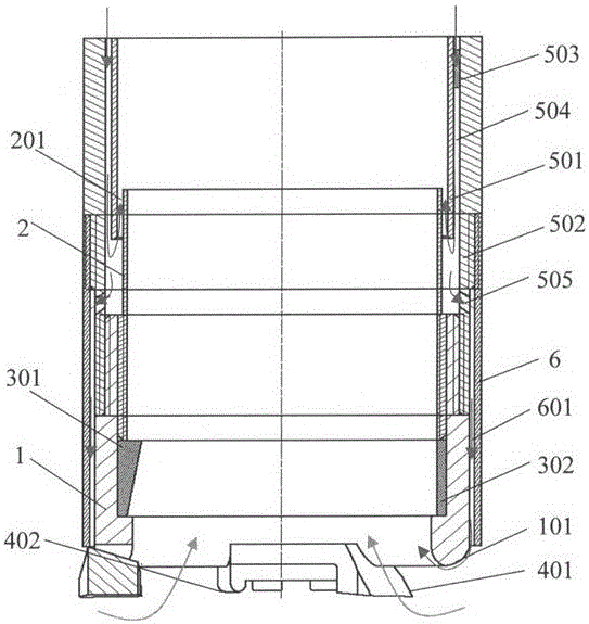
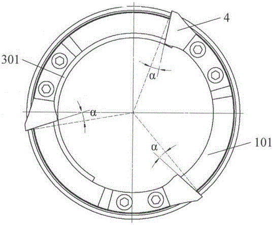
[0016] see figure 1 , figure 2 , image 3 with Figure 4 As shown, this embodiment includes a drill bit body 1, a nozzle holder 2, an ice core snap-off device 3, a cutting head 4, a double-wall joint 5, a shroud 6 and a shoe 7, and the drill bit body 1 and the double-wall joint 5 The outer pipe 502 of the double-walled joint is threaded, and the bottom lip of the drill body 1 is fixed with several cutting bits 4 by bolts. Chips migrate to the center channel. The cutting depth of the cutting bit 4 is controlled by the pad shoe 7, and the pad shoe 7 is connected with the cutting bit 4 and the drill bit body 1 by bolts. The bottom lip surface of the drill body 1 is an arc-shaped surface 101 . The nozzle pipe 2 is connected with the drill bit body 1 by threads, and the ice core snap-off device 3 is fixed on the inner step of the drill bit body 1 .

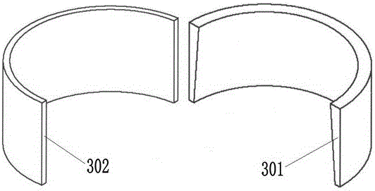
[0017] The ice core snapping device 3 is composed of a semicircular wedge structure 301 and a semicircular structure 302 , and...


PUM


Abstract

The invention discloses an air reverse circulation continuous coring ice drill bit. A drill bit body of the air reverse circulation continuous coring ice drill bit is in threaded connection with a double-walled connector external pipe of a double-walled connector. A plurality of cutting tool bits are fixed to the bottom lip surface of the drill bit body through bolts. The front corner of each cutting tool bit inclines towards a drill bit central channel by an inclination angle alpha of 5-15 degrees. A cushion shoe is connected with the cutting tool bits and the drill bit body through bolts. A support spraying tube is connected with the drill bit body through threads. An ice core breaking device is fixed to a step inside the drill bit body. The support spraying tube and a double-walled connector internal pipe form a circular seam gap. The double-walled connector external pipe and the double-walled connector internal pipe form an annular space, and a supporting block is arranged between the double-walled connector external pipe and the double-walled connector internal pipe. A fairing is connected with the double-walled connector external pipe through threads. The fairing and the outer wall of the drill bit body form an annular spray nozzle. A plurality of gas inlet holes are formed in the double-walled connector external pipe. According to the air reverse circulation continuous coring ice drill bit, the drilling efficiency is improved, the ice core recovery rate is increased, accordingly the construction period of polar region drilling projects is greatly shortened, and the risk of complex accidents in a hole is lowered.

Description

technical field [0001] The patent of the invention belongs to the technical field of polar drilling, and relates to a drill bit for continuous air core drilling in ice layers with reverse circulation. Background technique [0002] Polar ice covers about 10% of the global land area, and its natural environment is of great value to human beings. Compared with other climate proxy indicators, the polar ice cap has the characteristics of large amount of information, good fidelity, high time resolution, large time scale range, and wide distribution area due to the low temperature and far away from human pollution. one of the key areas. Obtaining high-quality ice cores through ice core drilling technology has become an important research direction of polar science, and has important scientific significance and social value for the development of human society and the understanding of nature. However, affected by the harsh climate and surface ice and snow environment, polar drilli...

Claims


Application Information

Patent Timeline
IPC IPC(8): E21B10/02E21B10/60E21B25/10
CPCE21B10/02E21B10/605E21B25/10
Inventor 陈宝义曹品鲁陈云望刘苗苗龙翔赵齐
Owner JILIN UNIV
Why Eureka
Try Eureka