
Method for obtaining an indication, in particular a starting indication of a possible faulty load condition of a multi-phase electric motor

A technology for multi-phase motors and load conditions, applied in the direction of motor control, measuring electricity, electrical components, etc., can solve problems such as insufficient protection, time delay of overheating identification devices, damage, etc.

Active Publication Date: 2017-05-10
ELMOS SEMICON SE
View PDF11 Cites 7 Cited by
  • Summary
  • Abstract
  • Description
  • Claims
  • Application Information

AI Technical Summary

Problems solved by technology

But the power transistor can still heat up to such an extent in this case that damage is caused, which happens so quickly that even the overheating detection device cannot provide sufficient protection due to its time delay

Method used


Image

  • Method for obtaining an indication, in particular a starting indication of a possible faulty load condition of a multi-phase electric motor
  • Method for obtaining an indication, in particular a starting indication of a possible faulty load condition of a multi-phase electric motor
  • Method for obtaining an indication, in particular a starting indication of a possible faulty load condition of a multi-phase electric motor

Examples


Embodiment Construction

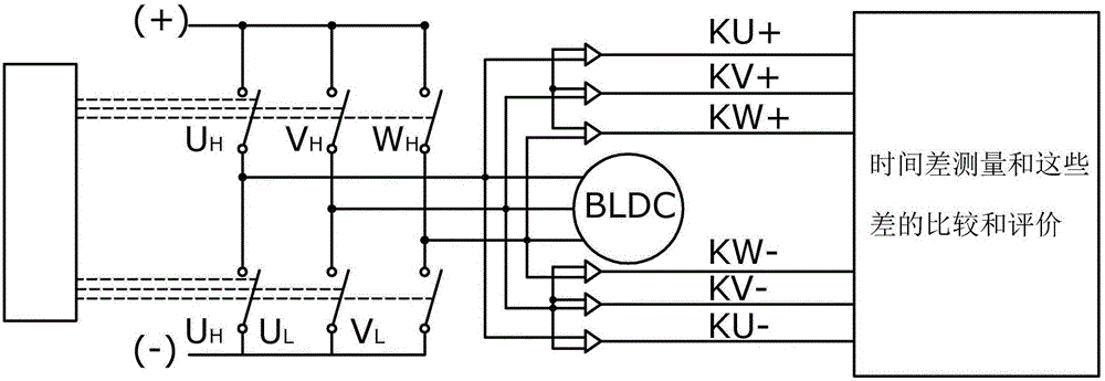
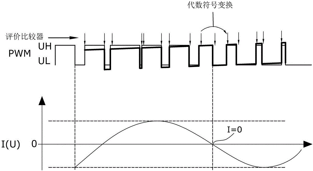
[0146] The invention is based on the insight that when driving an inductive load such as a motor, a comparator is used to determine whether a transistor has a positive voltage drop (under load) or a negative voltage drop (in the case of inductive feedback) in the on-state case).

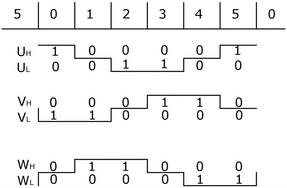
[0147] This is an indication of the direction of current flow through the driver (switch). In the case of an inductive load such as a motor, the point in time at which the current direction is reversed is of course determined on the one hand by the control of the modulation motor, but also on the other hand by the behavior of the coil current which is known to follow the modulation voltage. The expected value for when the transition from positive to negative voltage drop will occur (ie the current through the corresponding driver drops to zero) is predetermined by the PWM modulation of the motor and the motor parameters.

[0148] If the position of the algebraic sign transformation of one terminal (...


PUM


Abstract

According to the invention, the electric motor is electrically commutated with the aid of circuitry, in which the phase current experiences a zero crossing at certain time points per motor phase. Owing to the inductive load portion, the time of said zero crossing of a phase current occurs at different times to the time of the zero crossing that would arise with purely ohmic loads. Without a faulty load condition, the time of said zero crossing is within an expected value range (e.g., expected time window) which can be determined by the circuitry, the ambient conditions and by diverse motor parameters. According to the method, during occurrence of the high-side and / or low-side phase connection predetermined in the circuitry, it is determined whether and when the current through the switched-on high-side or low-side switch becomes greater or smaller than a predeterminable threshold, in a particular case in the vicinity of the zero crossing, wherein said time measurement can extend in the case of a PWM control, if required, over one or more PWM cycles.

Description

[0001] This patent application claims priority from three German patent applications 10 2014 212 586.3, 10 2014 212 572.3 and 102014 212 626.6, all filed on June 30, 2014, which are hereby incorporated by reference into the subject matter of this patent application . technical field [0002] The invention relates to a method for obtaining an indication, in particular starting an indication, of a possible faulty load situation of a polyphase motor. Background technique [0003] Faulty load conditions in the motor are particularly critical when a short circuit occurs. Such a short circuit is usually detected by means of a voltage drop on the drain-source path of a driver transistor internal or external to the control unit via which the motor or other load is controlled. These voltage drops are usually assessed individually, ie on each phase of the motor. If the metrologically detected current is greater than the maximum permissible operating current, this means an external s...

Claims


Application Information

Patent Timeline
IPC IPC(8): H02P29/024H02P29/028
CPCH02P29/032H02P29/027G01R19/16547G01R31/343H02P29/024H02M1/32H02P29/0241H02P29/0243
Inventor 约尔格·哈茨池
Owner ELMOS SEMICON SE
Learn More