Manufacturing method of rubber roller for heat fixing, and rubber roller for heat fixing
一种制造方法、橡胶辊的技术,应用在应用电荷图形的电记录工艺、应用电荷图形的电记录工艺的设备、应用等方向,能够解决水溶性粉末无法充分溶出、高海绵体等问题
- Summary
- Abstract
- Description
- Claims
- Application Information
AI Technical Summary
Problems solved by technology
Method used
Image
Examples
no. 1 Embodiment approach
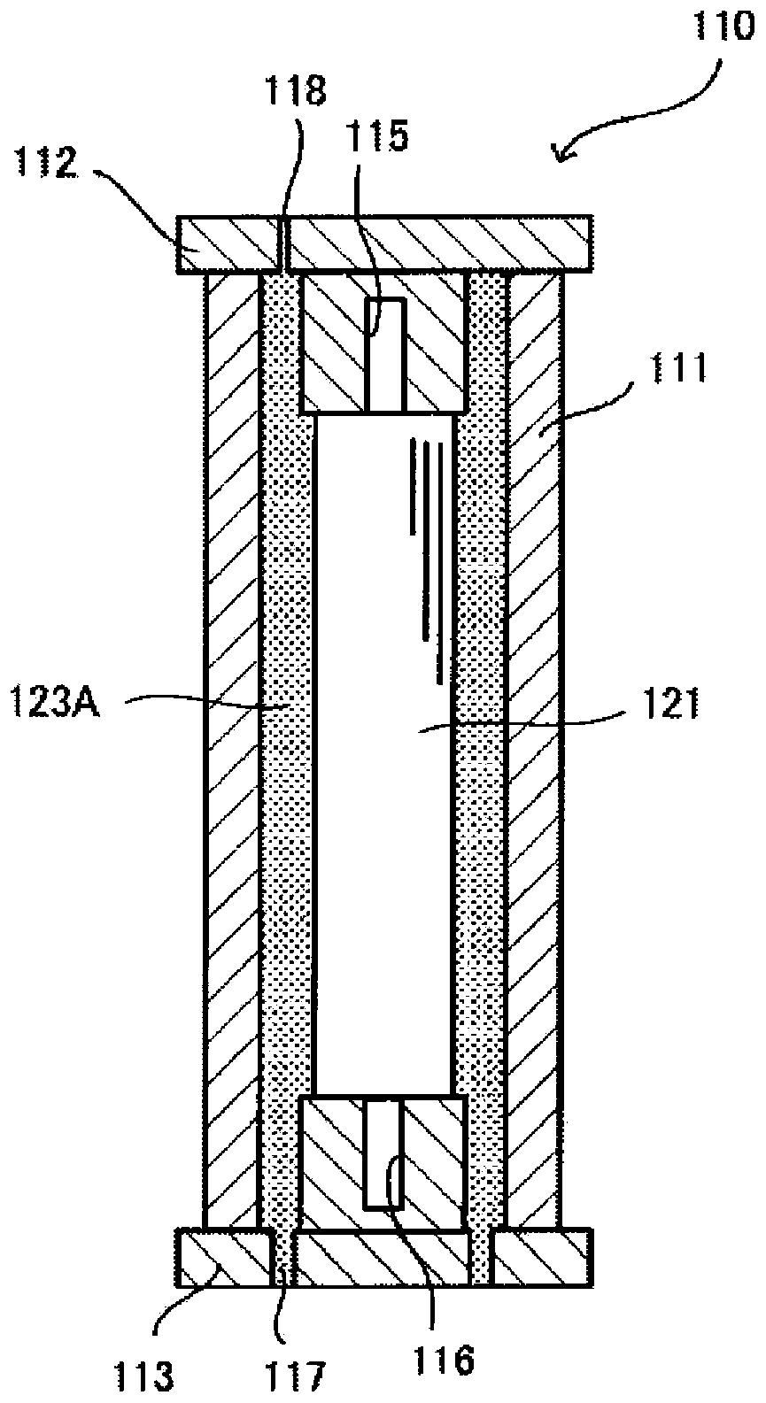
[0032] figure 1 It is a sectional view showing the manufacturing process of the heat-fixing rubber roller according to the embodiment of the present invention.
[0033] The cylindrical mold used in this embodiment is demonstrated.
[0034] Such as figure 1 As shown, the cylindrical mold 110 used in this embodiment is composed of an upright cylindrical mold 111, an upper plug body 112 and a lower plug body 113 fitted into the upper and lower parts of the cylindrical mold 111, respectively. Inside the upper plug body 112 and the lower plug body 113, there are mandrel holding holes 115, 116 for holding a metal mandrel 121 made of aluminum, iron, stainless steel, etc. as a base material in the cylindrical mold 111. concentric. A material injection hole 117 is provided on the lower plug body 113 , and a material discharge hole 118 is provided on the upper plug body 112 .
[0035] In the present embodiment, the cylindrical mold 111 of the cylindrical mold 110 configured in this ...
no. 2 Embodiment approach
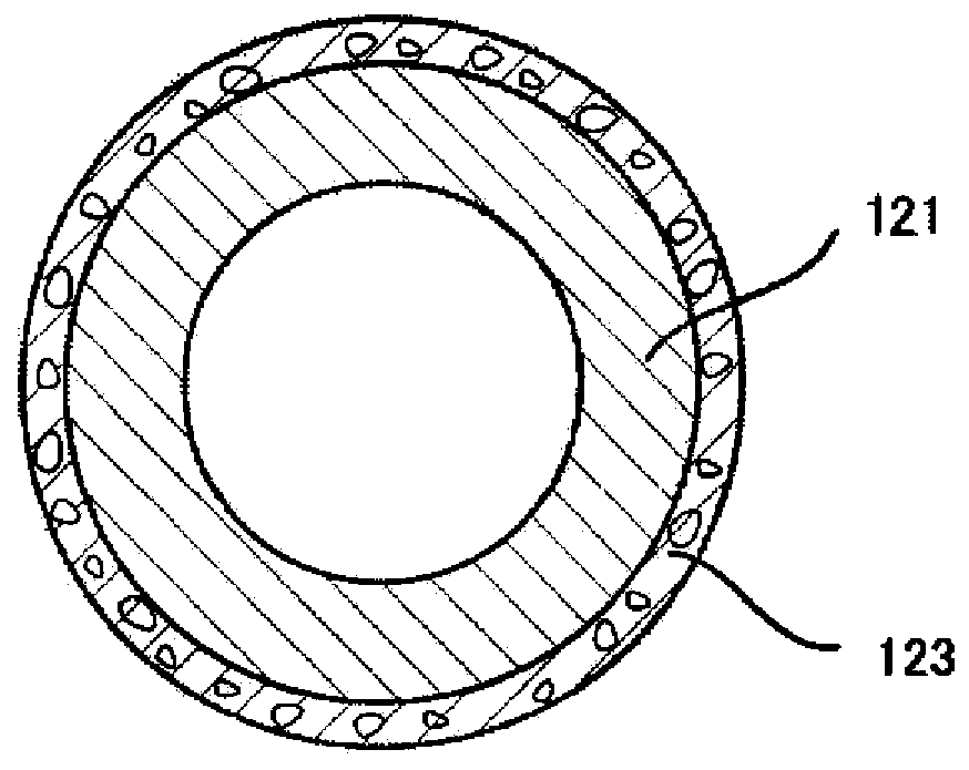
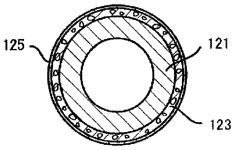
[0055] Such as image 3 The shown roller having a three-layer structure in which a metal mandrel 121 is sequentially coated with a foamed silicone rubber layer 123 and a release resin layer 125 composed of a release resin tube can use the above-mentioned figure 1 The cylindrical mold 110 shown in . Below, refer to Figure 4 , and will be described focusing on the points of change between the second embodiment and the already described first embodiment.
[0056] Figure 4 It is a cross-sectional view showing the manufacturing process of the heat-fixing rubber roller coated with a mold release resin according to the second embodiment of the present invention. figure 1 Common parts are denoted by the same symbols.
[0057] Such as Figure 4 As shown, in the present embodiment, the releasable resin tube 125A is inserted into the inner side of the cylindrical mold 111 holding the upright cylindrical mold 110, and both ends thereof are bent and fixed. Then, the metal mandrel 1...
Embodiment
[0062] Hereinafter, the present invention will be described more specifically by way of examples, but the present invention is not limited by these examples.
[0063] (Example)
[0064] Such as figure 1 As shown, a metal mandrel 121 made of aluminum having an outer diameter of 18 mm and having an outer diameter coated with primer #101 (Prizema ー #101, manufactured by Shin-Etsu Chemical Co., Ltd. (Shin-Etsu Chemical Industry Co., Ltd., trade name)) was inserted. In the cylindrical mold 111, the upper plug body 112 and the lower plug body 113 are respectively fitted into the upper part and the lower part of the cylindrical mold 111 so as to keep them concentric.
[0065] In addition, 25 parts by mass of triethylene glycol was mixed with 130 parts by mass of fine granulated sugar powder having a particle diameter of 10 to 200 μm obtained by pulverizing commercially available fine granulated sugar and sieving, and 100 parts by mass of triethylene glycol was added to the mixture. ...
PUM
| Property | Measurement | Unit |
|---|---|---|
| particle diameter | aaaaa | aaaaa |
| particle diameter | aaaaa | aaaaa |
| particle diameter | aaaaa | aaaaa |
Abstract
Description
Claims
Application Information
 - R&D
- Intellectual Property
- Life Sciences
- Materials
- Tech Scout
- Unparalleled Data Quality
- Higher Quality Content
- 60% Fewer Hallucinations
Browse by: Latest US Patents, China's latest patents, Technical Efficacy Thesaurus, Application Domain, Technology Topic, Popular Technical Reports.
© 2025 PatSnap. All rights reserved.Legal|Privacy policy|Modern Slavery Act Transparency Statement|Sitemap|About US| Contact US: help@patsnap.com


