Method for forming tin oxide layer by means of tin metal target

A technology of tin oxide and tin metal, which is applied in the direction of metal material coating process, coating, ion implantation plating, etc., can solve the problems of low stability and limited application possibility, and achieve the effect of reducing costs

Inactive Publication Date: 2017-05-10
RFTRON
View PDF7 Cites 1 Cited by
  • Summary
  • Abstract
  • Description
  • Claims
  • Application Information

AI Technical Summary

Problems solved by technology

For example, ITO (Indium Tin Oxide) has been developed and used as a transparent conductor, and ZnO is being developed as a transparent semiconductor, but its application as a transparent semiconductor is extremely limited due to its low stability.

Method used


Image

  • Method for forming tin oxide layer by means of tin metal target
  • Method for forming tin oxide layer by means of tin metal target
  • Method for forming tin oxide layer by means of tin metal target

Examples


Embodiment Construction

[0042] It should be noted that in the following description, only the parts necessary for understanding the embodiments of the present invention will be described, and the description of the remaining parts will be omitted without confusing the gist of the present invention.

[0043] The words or phrases used in this specification and claims that will be set forth below should not be construed as being limited to the commonly used meaning or the meaning in the dictionary, but should be based on the inventor's ability to explain his invention in the best way. The principle of properly defining the concept of terms is interpreted as the meaning and concept in accordance with the technical idea of ​​the present invention. Therefore, since the implementations described in this specification and the configurations shown in the drawings are only preferred implementations of the present invention and do not represent all technical ideas of the present invention, it should be understood ...


PUM

PropertyMeasurementUnit
thicknessaaaaaaaaaa
thicknessaaaaaaaaaa

Abstract

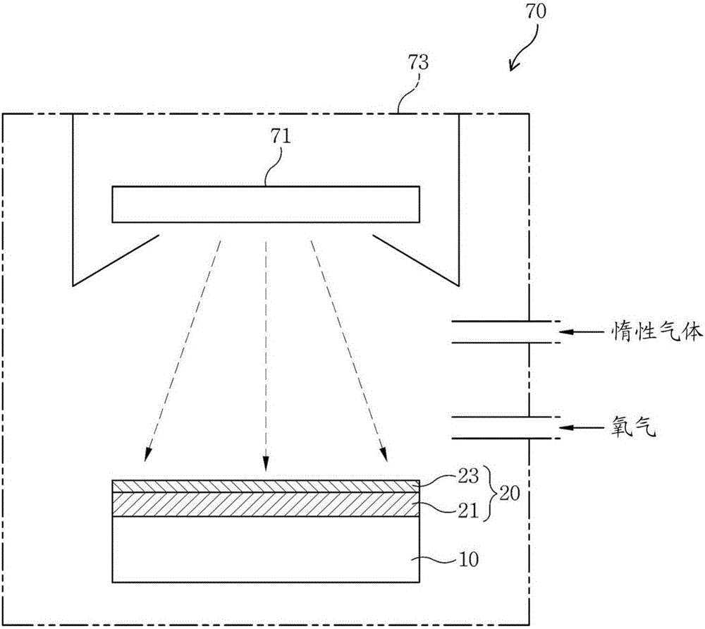
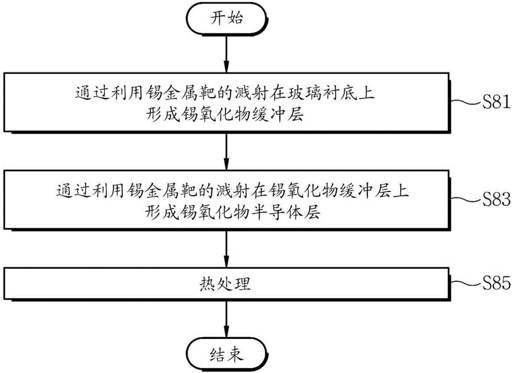
The present invention relates to a method for forming a tin oxide layer by means of a tin metal target, the method forming the tin oxide layer on a glass substrate by means of a tin metal target. Provided is a method for forming a tin oxide layer by means of a tin metal target, the method comprising the steps of: forming a tin oxide buffer layer (SnO2) on a glass substrate by means of sputtering using a tin metal target; and forming a tin oxide semiconductor layer (SnO2-x where 0 < x <= 0.01) on the tin oxide buffer layer by means of sputtering using a tin metal target.

Description

technical field [0001] The present invention relates to a method for forming a tin oxide layer, and in more detail, relates to a method for forming a tin oxide layer using a tin metal target to form a tin oxide layer on a glass substrate. Background technique [0002] Currently, the integration of the functions of electronic components and display components has become one of the trends in information technology (information technology). An electronic display device is a device that combines the functions of such electronic components and display components. [0003] In particular, in today's information society, the role of electronic display devices is becoming more and more important, and various electronic display devices are being widely used in various industrial fields. The field of such electronic display devices has been continuously developed, and electronic display devices having new functions that meet the diverse needs of the information society are being conti...

Claims


Application Information

Patent Timeline
Patent Type & Authority Applications(China)
IPC IPC(8): C23C14/00C23C14/08H01L21/203H01L31/18H01L51/56
CPCH01L21/203C23C14/0042C23C14/086H01L31/1884H10K71/00H01L21/02422H01L21/02483H01L21/02565H01L21/02631H01L29/66969H01L29/78603H01L29/7869H01L29/78696H01L31/022475H01L21/02107Y02E10/50C23C14/0036H01L21/02535H01L21/324
Inventor 车国麟任志淳
Owner RFTRON
Why Eureka
Try Eureka