
Vehicle Pneumatic Tires

A technology for pneumatic tires and vehicles, applied in vehicle parts, tire parts, tire treads/tread patterns, etc., can solve problems such as detrimental drainage capacity, and achieve the effect of good operating performance

Active Publication Date: 2019-04-23
CONTINENTAL REIFEN DEUTSCHLAND GMBH
View PDF5 Cites 0 Cited by
  • Summary
  • Abstract
  • Description
  • Claims
  • Application Information

AI Technical Summary

Problems solved by technology

It may therefore be advantageous to form as few grooves as possible in the tread area, however this may strongly impair the tread's ability to drain water quickly and effectively

Method used


Image

  • Vehicle Pneumatic Tires
  • Vehicle Pneumatic Tires
  • Vehicle Pneumatic Tires

Examples


Embodiment Construction

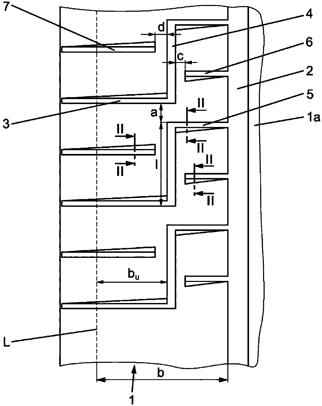
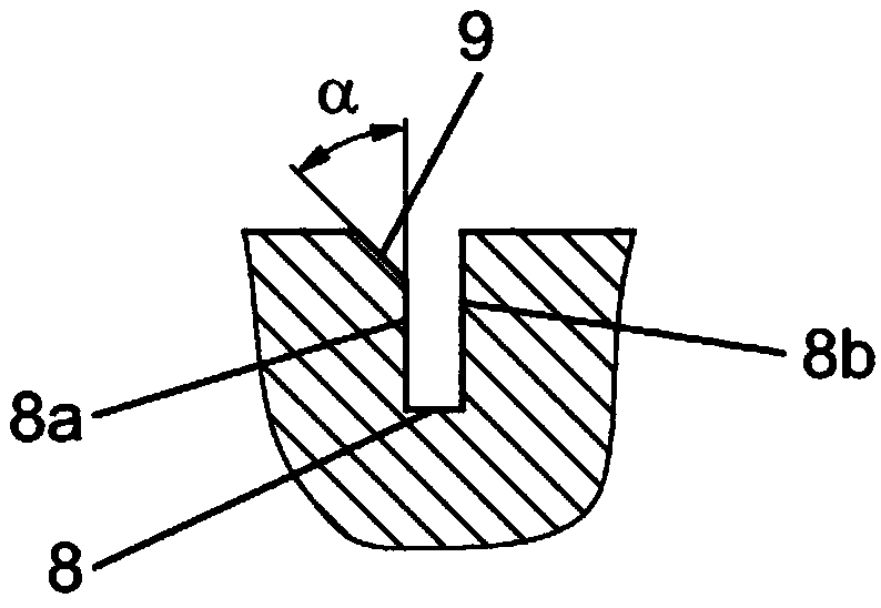
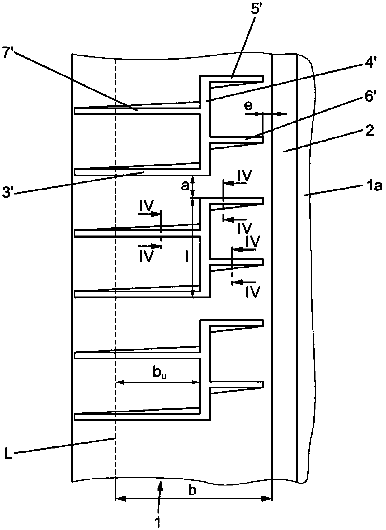
[0018] figure 1 and image 3 A top view of a circumferential section of a tread band 1 of a tread of a vehicle pneumatic tire, in particular a tread for passenger motor vehicles, trucks or the like, is shown. The tread bands 1 shown are arranged in the outer part of a tread pattern configured as a so-called "asymmetrical" tread pattern. Such tread patterns have, in the two tread halves, structurally differently configured profiles which are correspondingly implemented with respect to certain properties of the tire or tread. The tread bands 1 shown are located on the "outer shoulder" of the tire, which in a known manner is the shoulder-side area of ​​the tire that is mounted on the vehicle Tires are visible at the outside of the vehicle. The line L marked on the left side of the tread band 1 in these figures characterizes an edge of the tread, that is, the edge of the ground-contacting surface or bottom bearing surface, which complies with the E.T.R.T.O. Standard (load at 7...


PUM


Abstract

The invention relates to vehicle tyres comprising a tread which, in relation to tyres mounted on the vehicle, has a profile strip (1) arranged on the outer shoulder, said profile strip being separated from additional profile elements by a circumferential groove (2) running in a circumferential direction, wherein short grooves (4, 4') run in the profile strip (1) in a circumferential direction, which short grooves are at a distance to one another and aligned with one another, and on one end of which a respective transverse groove (3, 3') is connected, said transverse groove running in the direction of and beyond the tread edge (L), and on the other ends of which a respective transverse groove (5, 5') is connected, said transverse groove running in the direction of the circumferential groove (2). A respective additional transverse groove (6, 6', 7, 7') runs respectively midway between the transverse grooves (3, 3') which neighbour one another in the circumferential direction and which are connected to each first end of the short grooves (4, 4'), and runs respectively midway between the transverse grooves (5, 5') which neighbour one another in the circumferential direction and which are connected to each other end of the short grooves (4, 4').

Description

technical field [0001] The present invention relates to a vehicle pneumatic tire having a tread having a tread band arranged at the outer shoulders, as viewed from the tire mounted on the vehicle, the tread band passing through a The surrounding circumferential sipe is separated from the other sipe, wherein short sipe running in the circumferential direction, substantially flush with each other and spaced apart from each other run in the tread band, correspondingly one in the sipe A transverse groove running in the direction of the tread edge and beyond the tread edge adjoins one end of the short grooves and correspondingly a transverse groove running in the direction of the circumferential groove adjoins the other end of the short grooves. Background technique [0002] A tire optimized in terms of its handling properties should have lugs in the tread in the region of its outer shoulders, these lugs being embodied as solid and stable as possible. It may therefore be advanta...

Claims


Application Information

Patent Timeline
Patent Type & Authority Patents(China)
IPC IPC(8): B60C11/03B60C11/13
CPCB60C11/0304B60C11/0306B60C11/1392B60C2011/036B60C2011/039
Inventor 乌尔里希·贝尔
Owner CONTINENTAL REIFEN DEUTSCHLAND GMBH
Learn More