
A photovoltaic panel steering device

A technology for steering devices and photovoltaic panels, applied in photovoltaic power generation, photovoltaic modules, photovoltaic module support structures, etc., can solve problems such as the reduction of photovoltaic panel power generation efficiency, and achieve the effect of improving photovoltaic conversion efficiency

Inactive Publication Date: 2019-04-02
NANJING GREEN NEW ENERGY RES INST CO LTD
View PDF4 Cites 0 Cited by
  • Summary
  • Abstract
  • Description
  • Claims
  • Application Information

AI Technical Summary

Problems solved by technology

After the traditional photovoltaic panel is generally installed, its facing direction is fixed, but the position of the sun is constantly changing throughout the day. Because there is a certain angle between the direction of the panel and the direction of sunlight radiation, the power generation efficiency of the photovoltaic panel is greatly reduced.

Method used


Image

  • A photovoltaic panel steering device
  • A photovoltaic panel steering device
  • A photovoltaic panel steering device

Examples


Embodiment 1

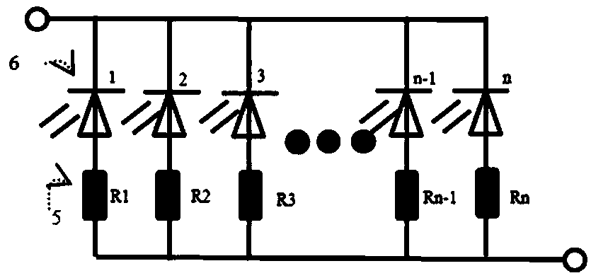
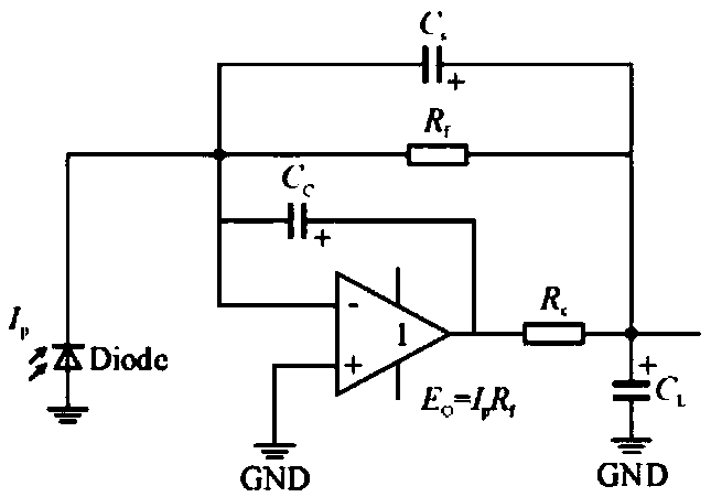
[0020] as attached figure 1 to attach Figure 4 As shown, a photovoltaic panel steering device of the present invention includes an optical lens 1, a photodiode circuit array 2, an electric elevator 3 and a photovoltaic panel 4, the optical lens 1 is located directly above the photodiode circuit array 2 and is connected to the photodiode circuit array 2 The spacing is the back focal length of the optical lens 1, the photodiode circuit array 2 includes a plurality of photodiodes 6 and a resistor 5 corresponding to each photodiode 6, the two ends of the photodiode circuit array 2 are arranged in a downward curved shape, and the photodiodes The output voltage of the circuit array 2 controls the lifting height of the electric elevator 3. The upper end of the electric elevator 3 is connected to one end of the photovoltaic panel 4. The initial state of the photovoltaic panel 4 is parallel to the ground. The middle of the photovoltaic panel 4 is supported by a fulcrum. The electric e...

Embodiment 2

[0025] In this embodiment, as attached Figure 5 As shown, the resistor 5 in the photodiode circuit array 2 is a sliding rheostat, and the resistance values ​​of the resistor 5 are arranged in an equal difference order from left to right, which can be arranged in a decreasing order or increasing arrangement, and the rest of the structure is the same as Example 1 is the same. Since the positions of the sliding rheostats connected to each photodiode 6 are different, the resistors connected in series are also different in size, so the output voltage will also be different, and the lifting height of the electric elevator 3 will also change accordingly. Repeating the above process, at any time throughout the day, the photovoltaic panel 4 is always kept perpendicular to the direction of sunlight radiation.


PUM


Abstract

The invention a photovoltaic panel diverting device, comprising an optical lens, a photoelectric diode circuit array, an electric lift and a photovoltaic panel; the optical lens is positioned right above the photoelectric diode circuit array, a distance from the optical lens to the photoelectric diode circuit array is a rear focal length of the optical length, the photoelectric diode circuit array includes a plurality of photoelectric diodes and a resistor corresponding to every photoelectric diode, two ends of the photoelectric diode circuit array are arranged in downwardly bent form, output voltage of the photoelectric diode circuit array controls lifting height of the electric lift, the upper end of the electric lift is connected to one end of the photovoltaic panel, the photovoltaic panel is parallel to a ground initially, and the middle of the photovoltaic panel is supported by a fulcrum. The photovoltaic panel diverting device enables the photovoltaic panel to face sun constantly throughout the day, direct solar radiation is received maximally, and photovoltaic conversion efficiency is improved.

Description

technical field [0001] The invention relates to the field of new energy technology, in particular to a photovoltaic panel steering device. Background technique [0002] Energy and the environment are the basis for human survival and development, and economic and social development is increasingly limited by the supply of energy. Solar energy is a clean, sustainable energy source. After traditional photovoltaic panels are generally installed, the direction they face is fixed, but the position of the sun is constantly changing throughout the day. Because there is a certain angle between the direction of the panels and the direction of sunlight radiation, the power generation efficiency of photovoltaic panels is greatly reduced. Contents of the invention [0003] The technical problem to be solved by the present invention is to overcome the deficiencies of the prior art, and provide a photovoltaic panel steering device that makes the photovoltaic panel face the sun all the t...

Claims


Application Information

Patent Timeline
Patent Type & Authority Patents(China)
IPC IPC(8): H02S40/22H02S20/32F24S30/20
CPCY02E10/47Y02E10/52
Inventor 刘海洋贾艳刚罗韬方坤李潺文邱宏善
Owner NANJING GREEN NEW ENERGY RES INST CO LTD
Learn More