
Luminous display with front double flat backward recessed gate controlled convex surface upper-lower ripple edge cathode structure

A technology of light-emitting display and cathode structure, which is applied in the direction of image/graphic display tube, cathode ray tube/electron beam tube, electrode device and related components, etc., and can solve the problems of high power loss of light-emitting display, gate structure burnt damage, etc.

Active Publication Date: 2017-05-10
重庆高新技术产业研究院有限责任公司
View PDF6 Cites 0 Cited by
  • Summary
  • Abstract
  • Description
  • Claims
  • Application Information

AI Technical Summary

Problems solved by technology

Since the gate is located directly above the carbon nanotube layer, and a positive potential is applied to the gate, it is inevitable to attract and intercept the electrons emitted by the carbon nanotube layer; If there are too many electrons trapped, it will cause a large power loss of the light-emitting display, and in severe cases, the gate structure will be burned and damaged

Method used


Image

  • Luminous display with front double flat backward recessed gate controlled convex surface upper-lower ripple edge cathode structure
  • Luminous display with front double flat backward recessed gate controlled convex surface upper-lower ripple edge cathode structure
  • Luminous display with front double flat backward recessed gate controlled convex surface upper-lower ripple edge cathode structure

Examples


Embodiment Construction

[0050] The present invention will be further described below in conjunction with the accompanying drawings and embodiments, but the present invention is not limited to this embodiment.

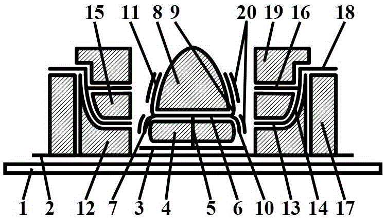
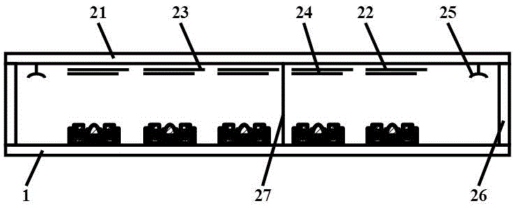
[0051] The light-emitting display with front double flat rear concave gated convex upper and lower corrugated edge cathode structure of this embodiment is shown in Fig. 1, Fig. 2 and Fig. 3. A vacuum chamber formed by a glass frame 26; an anode square film layer 22, an anode silver wiring layer 23 connected to the anode square film layer 22 and a phosphor layer prepared on the anode square film layer 22 are arranged on the upper pressure-resistant sealing flat plate 24. On the lower pressure-resistant sealing plate 1, there are front double straight and rear concave gate-controlled convex surface and upper and lower corrugated cathode structures; getter 25 and support column 27 are located in the vacuum chamber as an accessory component.

[0052] The front double straight back concave gated co...


PUM


Abstract

The invention relates to a luminous display with a front double flat backward recessed gate controlled convex surface upper-lower ripple edge cathode structure. The luminous display comprises a vacuum chamber composed of an upper anti-pressure seal flat plate, a lower anti-pressure flat plate and a transparent glass frame, and attached components including degasifiers and support columns located in the vacuum chamber, wherein anode square film layers, anode silver connection wire layers connected with the anode square film layers, and fluorescent powder layers prepared on the anode square film layers are arranged on the upper anti-pressure seal flat plate; and the front double flat backward recessed gate controlled convex surface upper-lower ripple edge cathode structure is arranged on the lower anti-pressure seal flat plate. The luminous display has the advantages of high luminous brightness, adjustable luminous grayscale, excellent performance, a stable and reliable fabrication process, and high finished product rate.

Description

technical field [0001] The present invention belongs to the fields of display technology, microelectronic science and technology, integrated circuit science and technology, vacuum science and technology, optoelectronic science and technology and nano science and technology, and relates to a flat field emission display production, specifically related to the production of planar field emission luminescent displays of carbon nanotube cathodes, and in particular to the production and production process of a luminescent display with double front flat and rear concave gated convex upper and lower corrugated edge cathode structures. Background technique [0002] Carbon nanotubes are a semiconductor material with excellent properties, which are very suitable for use as cold cathodes for flat-panel light-emitting displays: due to the extremely high temperature resistance of carbon nanotubes, the phenomenon of cathode burn-out in flat-panel light-emitting displays is completely elimin...

Claims


Application Information

Patent Timeline
IPC IPC(8): H01J29/04H01J29/46H01J31/12H01J1/304
CPCH01J1/304H01J29/04H01J29/467H01J31/127
Inventor 李玉魁王凤歌
Owner 重庆高新技术产业研究院有限责任公司
Learn More