Eureka AIR delivers breakthrough ideas for toughest innovation challenges, trusted by R&D personnel around the world.

Semi-active reflecting mirror surface supporting and positioning system

A mirror surface, semi-active technology, applied in installation, optics, instruments, etc., can solve the problems of large structural limitations, complex systems, and high cost

Inactive Publication Date: 2017-05-10
NANJING UNIV OF AERONAUTICS & ASTRONAUTICS
View PDF3 Cites 1 Cited by
  • Summary
  • Abstract
  • Description
  • Claims
  • Application Information

AI Technical Summary

Problems solved by technology

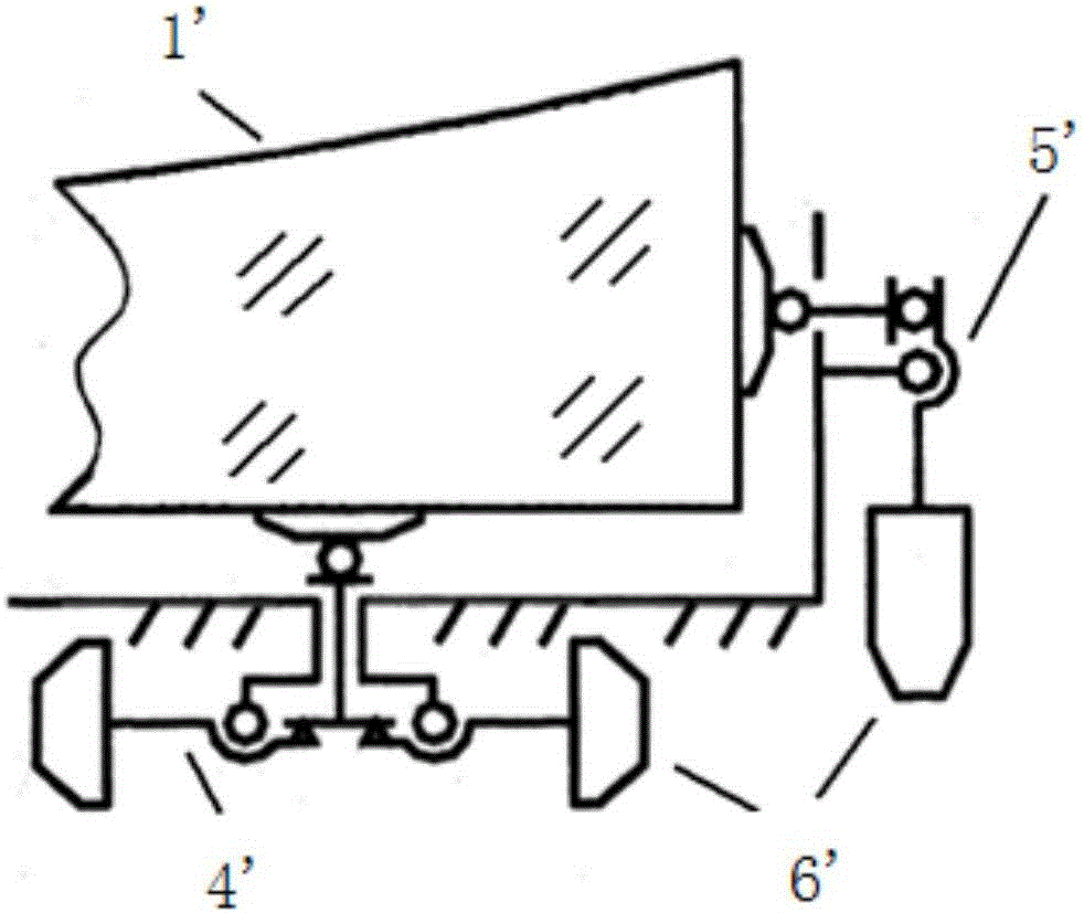
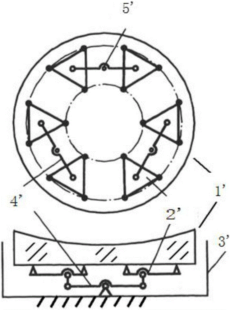
[0004] The disadvantages of the above-mentioned mirror support method are: the structure of the axial support and lateral support based on the traditional passive support is complex, and the structure is relatively limited, and the increase of support points will lead to the superposition of structural layers; while the advanced active support method requires real-time detection. Closed-loop control, complex system, high cost

Method used


Image

  • Semi-active reflecting mirror surface supporting and positioning system
  • Semi-active reflecting mirror surface supporting and positioning system
  • Semi-active reflecting mirror surface supporting and positioning system

Examples


Embodiment Construction

[0035] The following will clearly and completely describe the technical solutions in the embodiments of the present invention with reference to the accompanying drawings in the embodiments of the present invention. Obviously, the described embodiments are only some, not all, embodiments of the present invention. The following description of at least one exemplary embodiment is merely illustrative in nature and in no way taken as limiting the invention, its application or uses. Based on the embodiments of the present invention, all other embodiments obtained by persons of ordinary skill in the art without creative efforts fall within the protection scope of the present invention. Relative arrangements of components and steps are set forth in these embodiments unless specifically stated otherwise. Expressions and numerical values ​​do not limit the scope of the present invention. At the same time, it should be understood that, for the convenience of description, the sizes of th...


PUM


Abstract

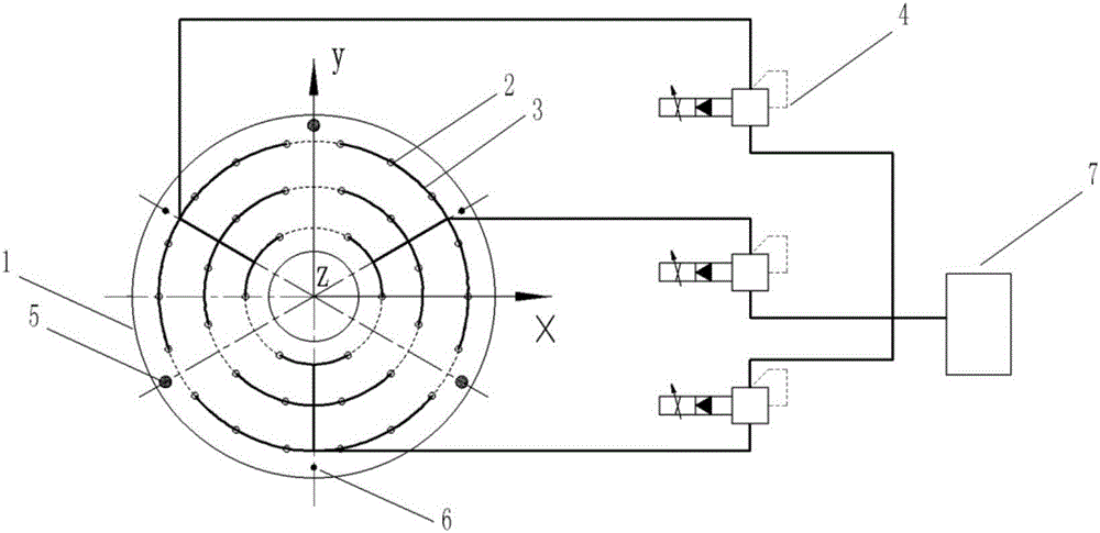
The invention discloses a semi-active reflecting mirror surface supporting and positioning system. The system is used for supporting and positioning a reflecting mirror surface and comprises a mirror surface supporting system and a mirror surface pose adjusting system; the mirror surface supporting system comprises an axial supporting system and a lateral supporting system, and the mirror surface pose adjusting system comprises an axial mirror surface pose adjusting system and a lateral mirror surface pose adjusting system; the axial mirror surface pose adjusting system is used for adjusting three freedom degrees, namely translation along the Z axis, rotation along the X axis and rotation along the Y axis, of the reflecting mirror surface and comprises a displacement actuator used for adjusting axial pose and an axial displacement sensor; and the axial supporting system is used for bearing component of gravity of the reflecting mirror surface in the axial direction, namely W*sintheta and comprises an axial fluid force actuator. Therefore, axial supporting and positioning of the reflecting mirror surface are based on fluid pressure control and drive, and axial precision positioning function of the mirror surface can be realized.

Description

technical field [0001] The invention relates to a positioning and supporting device, which is used for supporting and positioning a large precision optical reflection mirror, and is especially suitable for supporting and positioning a main mirror of a large astronomical telescope. Background technique [0002] Precision optical mirrors need stable and precise support and positioning. For example, in the process of tracking and observing celestial bodies with astronomical telescopes, the mirrors often need to start from the lowest pointing close to the ground level and turn to the highest pointing at the zenith, that is, often need to realize the pitch angle The range is from 0 degrees to 90 degrees, and it is necessary to ensure that the mirror surface always maintains the required surface shape accuracy and positioning accuracy during the tracking process. This requires good positioning and support of all mirrors of the astronomical telescope, especially the primary mirror....

Claims


Application Information

Patent Timeline
Patent Type & Authority Applications(China)
IPC IPC(8): G02B7/198
CPCG02B7/198
Inventor 杨德华
Owner NANJING UNIV OF AERONAUTICS & ASTRONAUTICS
Why Eureka
Eureka Blog
Learn More