
Unmanned aerial vehicle bridge bottom surface crack detection method and system

A crack detection and unmanned aerial vehicle technology, applied in control/adjustment systems, measuring devices, optical testing flaws/defects, etc., can solve problems such as systems that have not been implemented by anyone, and achieve low cost, high degree of automation, and high safety factor. Effect

Inactive Publication Date: 2017-05-10
WUHAN UNIV
View PDF4 Cites 80 Cited by
  • Summary
  • Abstract
  • Description
  • Claims
  • Application Information

AI Technical Summary

Problems solved by technology

The current UAV bridge bottom crack detection method and its system have not yet been realized

Method used


Image

  • Unmanned aerial vehicle bridge bottom surface crack detection method and system
  • Unmanned aerial vehicle bridge bottom surface crack detection method and system
  • Unmanned aerial vehicle bridge bottom surface crack detection method and system

Examples


Embodiment Construction

[0050] The invention provides a method and system for detecting cracks on the bottom surface of an unmanned aerial vehicle bridge. In order to make the object, technical solution and effect of the present invention more clear and definite, the present invention will be further described in detail below with reference to the accompanying drawings.

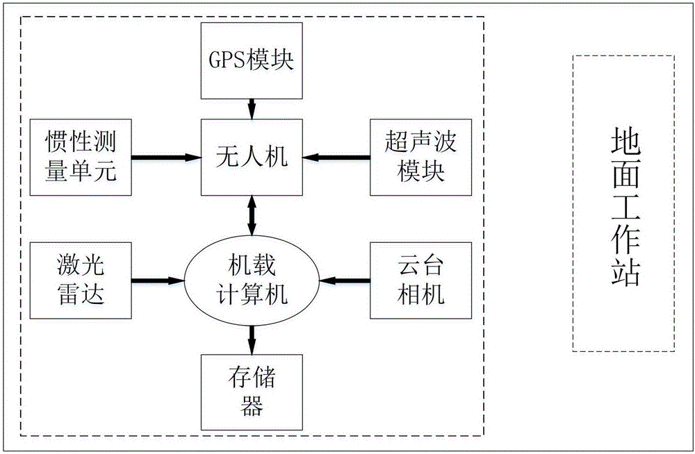
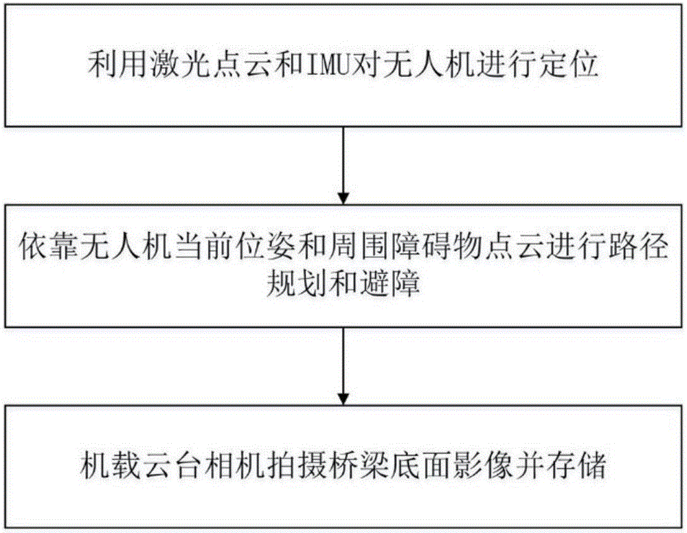
[0051] The present invention mainly includes two parts, the UAV end and the image data processing end of the ground workstation. The hardware structure and module schematic diagram reference of the UAV figure 1 , the drone-side workflow is as follows figure 2 . The drone end of the crack detection system on the bottom surface of the drone bridge includes the following steps:

[0052]Step S100: rely on the airborne lidar and inertial measurement unit (IMU) to locate the unmanned aerial vehicle flying under the bridge;

[0053] Step S200: rely on the current position and attitude of the unmanned aerial vehicle obtained by S100, a...


PUM


Abstract

The invention provides an unmanned aerial vehicle bridge bottom surface crack detection method and system. The unmanned aerial vehicle bridge bottom surface crack detection system comprises an unmanned aerial vehicle end and a ground workstation. The unmanned aerial vehicle end utilizes an airborne laser radar and an inertial measurement unit to position an unmanned aerial vehicle and form an unmanned aerial vehicle peripheral barrier point cloud to avoid barriers and plan a path; and an airborne platform camera photographs a bridge bottom surface at a constant frequency and stores a high-definition image into a memory. The ground workstation processes the photographed image, and splices an image between bridge piers to form a large-sized bridge bottom surface image; then the edge information in the image is acquired, the morphological corrosive expansion and connection are performed on the edge to extract a complete crack, and the crack is roughly positioned by virtue of a bridge pier position at which the spliced image is arranged; and finally the crack is evaluated, and information about the crack such as a length, a width, a distribution density and the like is analyzed and measured. The unmanned aerial vehicle bridge bottom surface crack detection method and system are high in automation degree, high in efficiency, high in safety coefficient, low in cost and wide in application prospect on the aspect of the bridge bottom surface route inspection.

Description

technical field [0001] The invention belongs to the technical field of image processing and unmanned aerial vehicles, and in particular relates to an autonomous flying technology under unmanned aerial vehicle bridges and a method for detecting cracks on the bottom surface of bridges based on unmanned aerial vehicle images. Background technique [0002] Over the years, a large number of concrete bridges have sprung up all over the country, and the safety of bridge projects is directly related to the lives of the people. The current status of crack detection on the bottom of bridges in my country is mainly manual, relying on bridge inspection vehicles and other large-scale machinery to send bridge inspection experts to the bottom of the bridge, look for cracks with the naked eye, and measure the size of cracks with crack observers or rulers. This manual detection method is inefficient, costly and has potential safety hazards. [0003] With the development of UAV technology, t...

Claims


Application Information

Patent Timeline
IPC IPC(8): G01N21/95G01N21/88G05D1/10
CPCG01N21/95G01N21/8851G01N2021/8854G01N2021/888G01N2021/8887G05D1/101
Inventor 杨文余淮张恒程文胜
Owner WUHAN UNIV
Learn More