
Method for improving measurement density of capacitive encoder and capacitive encoder

A technology for measuring density and encoder, which is applied to a method for improving the measuring density of capacitive encoders and the field of capacitive encoders, can solve the problems of inability to provide measurement information, low measuring density, unstable measuring density of capacitive encoders, etc. Increase the frequency, improve the measurement accuracy, and improve the effect of the measurement density

Active Publication Date: 2017-05-10
天津芯愿景软件有限公司
View PDF9 Cites 0 Cited by
  • Summary
  • Abstract
  • Description
  • Claims
  • Application Information

AI Technical Summary

Problems solved by technology

The measurement density of existing capacitive encoders is unstable, and sometimes the measurement density may drop so low that sufficient measurement information cannot be provided within a specified period of time

Method used


Image

  • Method for improving measurement density of capacitive encoder and capacitive encoder
  • Method for improving measurement density of capacitive encoder and capacitive encoder
  • Method for improving measurement density of capacitive encoder and capacitive encoder

Examples


Embodiment Construction

[0046] It should be noted that, in the case of no conflict, the embodiments of the present invention and the features in the embodiments can be combined with each other.

[0047] The present invention will be described in detail below with reference to the accompanying drawings and examples.

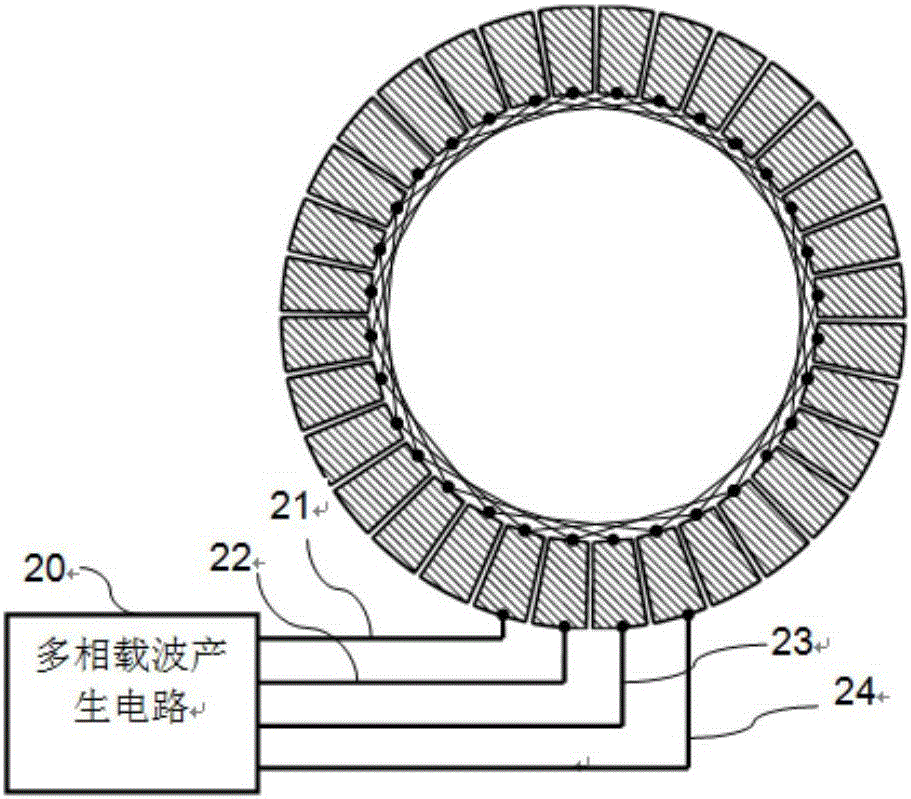
[0048] In one embodiment of the present invention, a capacitive encoder includes a multiphase carrier generation circuit 20, four variable capacitors, a demodulation circuit 30, and a motion direction detection circuit 60;

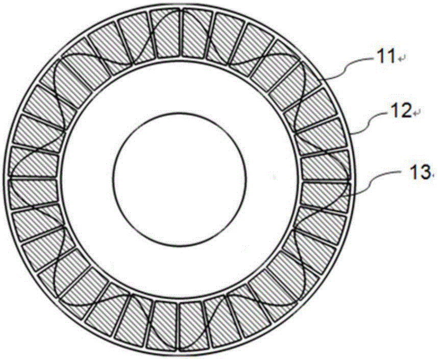
[0049] The variable capacitor includes a stator and a mover 13. There are two stators, which respectively include two plates of the capacitor, one of which is defined as the emitter plate 11, and the other is defined as the receiver plate 12; The mover 13 is located between the two pole plates and is made of a material whose dielectric constant is not equal to that of air, usually an insulating material whose dielectric constant is much greater than that of air; the ...


PUM


Abstract

The invention provides a capacitive encoder. The capacitive encoder comprises a multi-phase sine carrier wave generation circuit with a variable phase sequence and a direction detection circuit used for detecting a motion direction of a capacitive encoder mover. A detected direction signal is used for controlling the phase sequence of multi-phase carrier waves outputted by the multi-phase sine carrier wave generation circuit, when change of the motion direction of the mover is detected by the direction detection circuit, the phase sequence of the multi-phase carrier waves is changed by the multi-phase sine carrier wave generation circuit, so influence of the capacitive encoder mover on modulation waves is always blue shift whatever the motion direction of the capacitive encoder mover is; detection frequency of a demodulation circuit at each modulation wave period is fixed, modulation wave frequency is improved after blue shift of the modulation waves occurs, the demodulation circuit has more detection points within the same time, the position information can be more frequently outputted, and thereby measurement density of the capacitive encoder is improved.

Description

technical field [0001] The invention belongs to the technical field of capacitance encoders, in particular to a method for improving the measurement density of capacitance encoders and the capacitance encoder. Background technique [0002] In the field of motion detection, the well-known sensors are encoders, which are divided into linear encoders and rotary encoders. Among them, rotary encoders are widely used, because rotary motion can usually be converted into linear motion by motor rotation and conveyor belt. Rotary encoders include 3 types: photoelectric encoders, magnetoelectric encoders, and capacitive encoders. Compared with photoelectric encoders, capacitive encoders are more durable and low in cost, and can withstand harsh environments, such as shock, vibration, dust, etc. Compared with magnetic encoders, capacitive encoders can provide higher accuracy, Lower cost and ideal for applications requiring hollow shafts rather than solid shafts. Most linear encoders ar...

Claims


Application Information

Patent Timeline
Patent Type & Authority Applications(China)
IPC IPC(8): G01D5/24G01D5/241
CPCG01D5/24G01D5/241
Inventor 姚德超熊伟
Owner 天津芯愿景软件有限公司
Learn More