
Clutch for vehicle

A clutch and clutch ring technology, applied in clutches, friction clutches, mechanical drive clutches, etc., can solve the problem of increasing the volume of the clutch, and achieve the effect of reducing the size, reducing the working force and large torque transmission capacity.

Active Publication Date: 2017-05-10
HYUNDAI MOTOR CO LTD
View PDF8 Cites 8 Cited by
  • Summary
  • Abstract
  • Description
  • Claims
  • Application Information

AI Technical Summary

Problems solved by technology

[0003] As mentioned above, the clutch preferably has as small a volume as possible and as large a torque transmission capacity as possible, but generally in order to ensure a large torque transmission capacity, it is necessary to increase the volume of the clutch

Method used


Image

  • Clutch for vehicle
  • Clutch for vehicle
  • Clutch for vehicle

Examples


Embodiment Construction

[0053] Hereinafter, although preferred embodiments of the present invention will be described in detail with reference to the drawings, the present invention is not limited or limited to these embodiments. For reference, the same reference numerals denote substantially the same elements in this specification, and the contents described in other drawings can be cited and described according to this rule, and the contents that are obvious or redundant to those skilled in the art can be omitted.

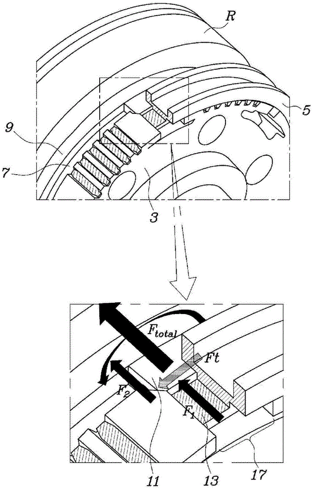
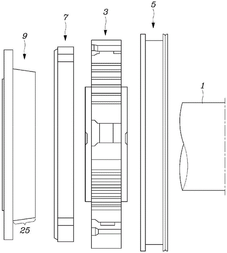
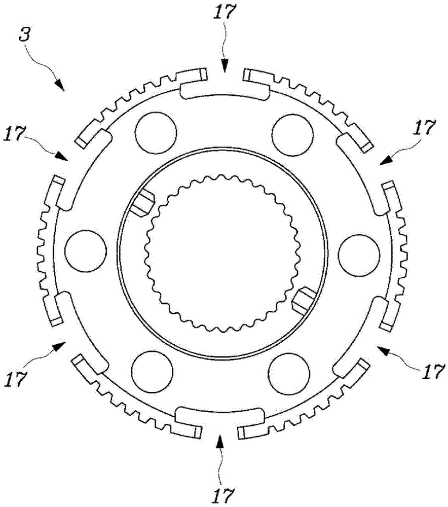
[0054] refer to Figure 1 to Figure 8 , the vehicle clutch of the embodiment of the present invention includes: a disc hub (hub) 3, which is arranged on the rotating shaft 1 in a state where the rotation is limited; The longitudinal direction of the above-mentioned rotating shaft (hereinafter referred to as the axial direction) can be provided in a manner of linear sliding; the clutch member 9 is provided in a state capable of relative rotation with respect to the above-mentioned rotati...


PUM


Abstract

The invention provides a clutch for a vehicle which includes a hub disposed on a rotary shaft such that a rotation thereof is restricted, a sleeve spline-coupled to an outer circumference of the hub, a clutch member disposed on the rotary shaft, and a clutch ring disposed between the clutch member and the hub, wherein the clutch ring is pressed against the clutch member by the sleeve and the hub, wherein the clutch ring comprises a pressed part to which an amount of force pressing against the clutch member is applied from the sleeve and the hub, the sleeve comprises pressing protrusions that transfer the axial driving force of the sleeve to the pressed part, and the hub comprises displacement converting portions that convert a relative rotational displacement with respect to the clutch ring into an axial linear displacement of the clutch ring.

Description

technical field [0001] The present invention relates to a vehicle clutch, and more specifically, to a structure of a clutch that can be used in a vehicle transmission or the like. Background technique [0002] A plurality of clutches are used in a transmission of a vehicle or the like to control power transmission between rotating bodies that rotate relative to each other. [0003] As described above, the clutch preferably has as small a volume as possible and as large a torque transmission capacity as possible, but in general, it is necessary to increase the volume of the clutch in order to ensure a large torque transmission capacity. [0004] In addition, in order for the clutch to transmit a large torque, the force for operating the clutch is correspondingly increased, so the size of a device for operating the clutch, such as an actuator, is relatively increased. [0005] The above-mentioned matters described as the background technology of the invention are only for inc...

Claims


Application Information

Patent Timeline
Patent Type & Authority Applications(China)
IPC IPC(8): F16D13/60F16D13/64
CPCF16D13/60F16D13/644F16D13/04F16D13/28F16D2023/065F16D13/38F16D2125/34
Inventor 朴钟闰
Owner HYUNDAI MOTOR CO LTD
Learn More