Power output structure of engine crankshaft front end

A crankshaft front end and power output technology, which is applied in the direction of machines/engines, mechanical equipment, etc., can solve the problems of unable to meet the transmission of the engine crankshaft front end, low load resistance capacity, low assembly efficiency, etc., achieve compact structure, improve resistance to sudden increase load ability, the effect of improving assembly efficiency

Inactive Publication Date: 2017-05-10
GUANGXI YUCHAI MASCH CO LTD
View PDF6 Cites 2 Cited by
  • Summary
  • Abstract
  • Description
  • Claims
  • Application Information

AI Technical Summary

Problems solved by technology

[0005] 1. The front end of the existing engine crankshaft only has timing gears that meet the power requirements of the engine itself, and there are no other power output gears, which cannot meet the requirements of the front end of the engine crankshaft to transmit the remaining power (such as hydraulic pumps) in the form of gear direct drive.
[0006] 2. The parts sleeved at the front end of the engine crankshaft can only be assembled by manual tooling for one-time assembly, with low precision and low assembly efficiency
[0007] 3. There is no pin connection between the parts sleeved at the front end of the engine crankshaft, and the division of power transmission is independent of each other. Under the impact of sudden load, the load resistance capacity is low

Method used


Image

  • Power output structure of engine crankshaft front end
  • Power output structure of engine crankshaft front end

Examples


Embodiment Construction

[0021] The specific embodiments of the present invention will be described in detail below in conjunction with the accompanying drawings, but it should be understood that the protection scope of the present invention is not limited by the specific embodiments.

[0022] Unless expressly stated otherwise, throughout the specification and claims, the term "comprise" or variations thereof such as "includes" or "includes" and the like will be understood to include the stated elements or constituents, and not Other elements or other components are not excluded.

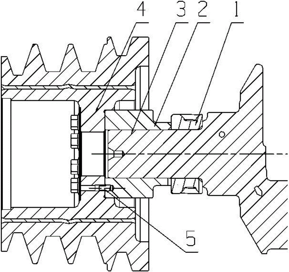
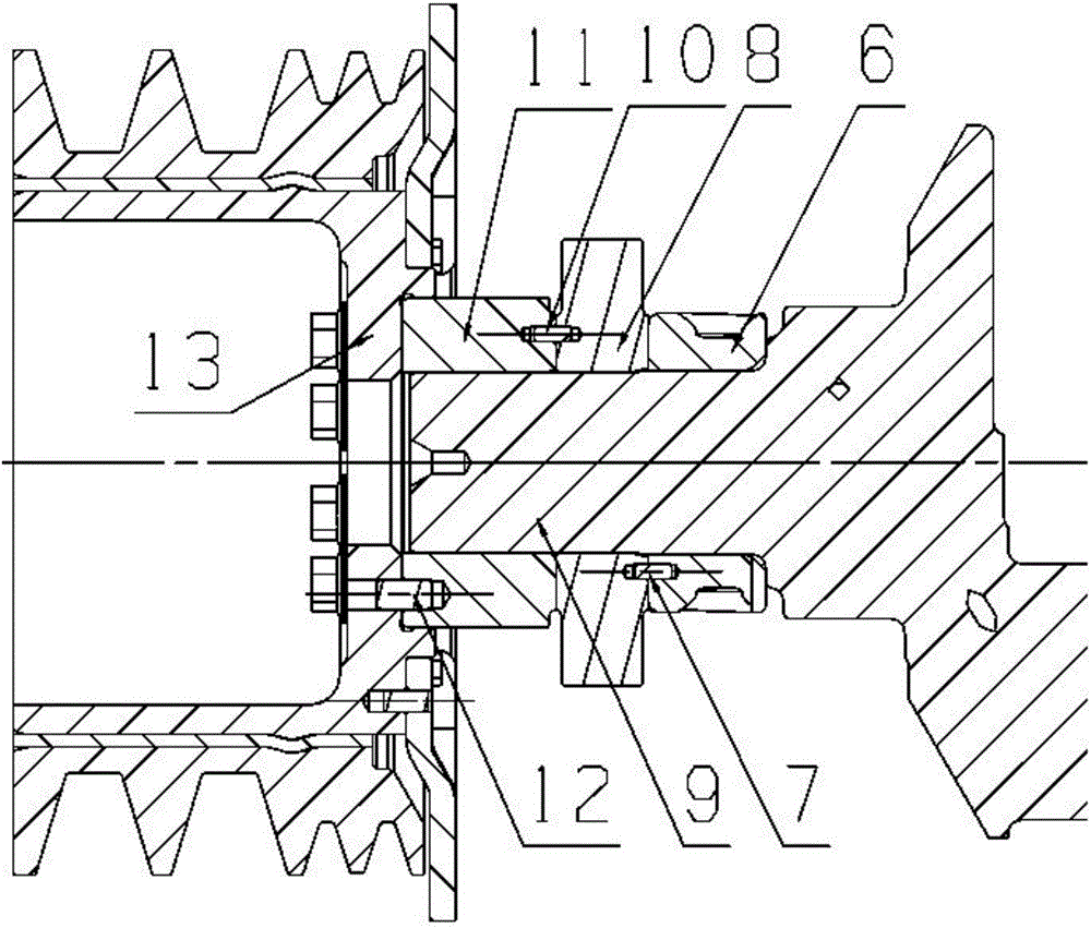
[0023] Such as figure 2 As shown, the power output structure of the engine crankshaft front end according to the specific embodiment of the present invention specifically includes: the engine crankshaft front end 9, the timing gear 6, the hydraulic pump transmission gear 8, the hydraulic pump transmission gear spacer 11 and the shock absorber 13, Wherein, the timing gear 6, the hydraulic pump transmission gear 8 and the h...


PUM


Abstract

The invention discloses a power output structure of an engine crankshaft front end. The power output structure of the engine crankshaft front end comprises the engine crankshaft front end, a timing gear, a fluid pump transmission gear, a liquid pump transmission gear spacer bush and an absorber, wherein the timing gear is arranged at the innermost end of the engine crankshaft front end in a sleeved mode through interference fit; the liquid pump transmission gear is close to the timing gear and is arranged at the engine crankshaft front end in a sleeved mode through interference fit; the liquid pump transmission gear spacer bush is arranged at the outermost end of the engine crankshaft front end in a sleeved mode through interference fit; the absorber is fixedly arranged at the outer end of the liquid pump transmission gear spacer bush in a sleeved mode through multiple bolts. According to the power output structure of the engine crankshaft front end, under the premise that the diameter and the length in an axial direction of the crankshaft front end are not changed, the engine crankshaft front end can simultaneously meet requirements of moving parts of the engine, external output of the absorber and power of the liquid pump, and the capacity of the engine crankshaft front end in resisting suddenly increased load is improved.

Description

technical field [0001] The invention relates to the field of engines, in particular to a power output structure at the front end of an engine crankshaft. Background technique [0002] Agricultural machinery requires the engine to have multiple power outputs. For example, the walking power of the harvester and the power of the hydraulic pump are transmitted through the pulley groove on the engine shock absorber and connected with a belt; Attenuation or failure, so agricultural machinery manufacturers require the engine to directly provide a hydraulic pump installation interface, and the engine is directly driven by gears to ensure transmission efficiency and reliability. Considering the structural layout, external dimensions and cost of the engine, the output structure is generally arranged at the front end of the crankshaft when the power demand is met. [0003] Existing engine crankshaft front end power output (engine crankshaft front end) generally only provides power for...

Claims


Application Information

Patent Timeline
Patent Type & Authority Applications(China)
IPC IPC(8): F02B67/00F02B67/04
CPCF02B67/00F02B67/04
Inventor 任勇杰石静胡国强陈剑涛李少明钟秀俊
Owner GUANGXI YUCHAI MASCH CO LTD
Why Eureka
Try Eureka