


Quick Research
Generate reliable direction feasibility study reports for your R&D in just a few steps.

Technical Q&A
Discover and master advanced knowledge NOW. Basics, ideas, possibilities, all at once.

Find Solutions
As an expert in R&D theories, this can generate solutions to your technical problems instantly.

Evaluate Feasibility
Analyze your overall solution with one click, know your potential R&D risks in advance.

Monitor Landscape
Get weekly tech updates, stay abreast of the latest tech innovations and key insights.
An automated hand washing and drying device
A kind of equipment and hand drying technology, which is applied in the field of automatic hand washing and drying equipment, can solve the problems of unsatisfactory use effect and poor scrubbing effect, and achieve the effect of easy maintenance, high scrubbing efficiency and large scrubbing area
- Summary
- Abstract
- Description
- Claims
- Application Information
AI Technical Summary
Problems solved by technology
Method used
Image

Examples
Embodiment 1
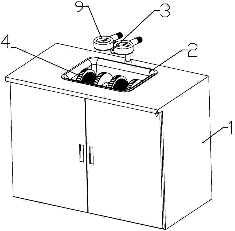
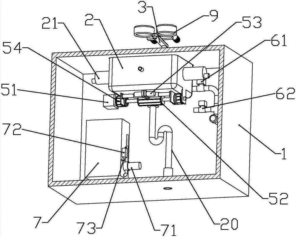
[0061] combine Figure 1 to Figure 12 As shown, this embodiment is an automatic hand-washing and drying equipment, including a cabinet body 1, a basin body 2 of non-ferromagnetic material installed on the cabinet body, installed on the upper rear side of the cabinet body and the water outlet is located above the basin body The faucet 3 in the middle position, and the scrubbing mechanism 4 installed in the basin body.
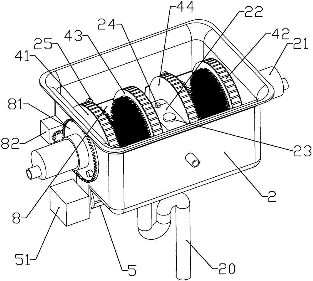
[0062] The scrubbing mechanism includes a first brush 41 and a second brush 42 installed on both sides of the tub, and a third brush 43 and a fourth brush 44 installed in the middle of the tub.
[0063] The two side walls of the basin body are symmetrically formed with lateral brush holders 21 in the shape of a horizontal circular tank, and the first brush and the second brush are horizontally slid and installed in the lateral brush holders on both sides; The outer end of the lateral brush seat is connected to the water pipe through a hose, and a second electro...
Embodiment 2
[0098] combine Figure 4 , Figure 5 and Figure 15 As shown, this embodiment makes the following improvements on the basis of Embodiment 1: an arc-shaped cover 8 is rotatably connected between the two telescopic tubes of the first brush and the second brush, and the arc-shaped cover has a center of circle An arc-shaped retaining wall with an angle of 150-200 degrees and two side plates integrally connected on both sides of the arc-shaped retaining wall, the side plates are formed with a connecting ring 801 matching the telescopic tube; A first magnet 83 is connected to the side plate of the cover; a transmission gear 81 is installed outside the lateral brush seat on the same side as the first magnet outside the basin, and a transmission gear 81 is connected with the first magnet through a magnetic field force on the transmission gear. The second magnet 84 that attracts tightly; the outer wall of the basin is equipped with a cover drive motor 82, and the output shaft of the ...
Embodiment 3
[0103] combine Figure 1 to Figure 3 , Figure 13 and Figure 14 In this embodiment, the following improvements are made on the basis of Embodiment 1 or 2: a connecting rod 91 is connected to the upper end of the faucet, and the two ends of the connecting rod are respectively connected to hand dryers 9 symmetrically arranged around the center relative to the faucet.
[0104] The hand dryer includes an annular air jet ring 92 and an air inlet tube 95 connected to the rear side of the air jet ring.
[0105] The upper part of the inner wall of the air injection ring is formed with an air injection port 921 facing vertically downward or obliquely downward, and the extension line intersects the axis of the air injection ring downward.
[0106] An axial flow fan and a heater are installed in the air inlet cylinder, and the heater is located on the side of the air outlet end of the axial flow fan; the tail of the air inlet cylinder is formed with an air inlet hole.
[0107] A sens...
PUM
 Abstract
Description
Claims
Application Information
 - R&D Engineer
- R&D Manager
- IP Professional
- Industry Leading Data Capabilities
- Powerful AI technology
- Patent DNA Extraction
Browse by: Latest US Patents, China's latest patents, Technical Efficacy Thesaurus, Application Domain, Technology Topic, Popular Technical Reports.
© 2024 PatSnap. All rights reserved.Legal|Privacy policy|Modern Slavery Act Transparency Statement|Sitemap|About US| Contact US: help@patsnap.com