
A powder metallurgy tempering furnace

A powder metallurgy and tempering furnace technology, applied in furnaces, heat treatment furnaces, furnace types, etc., can solve the problems of large oil fume, difficult to collect and process oil fume, and excessive oil fume concentration in the production workshop, and achieve the effect of reducing pollution.

Active Publication Date: 2018-06-08
TIANJIN FENGDONG CHENXU METAL TECHNOLOGY CO LTD
View PDF10 Cites 0 Cited by
  • Summary
  • Abstract
  • Description
  • Claims
  • Application Information

AI Technical Summary

Problems solved by technology

Different from non-powder metallurgy parts, due to the physical characteristics of powder metallurgy parts, it is difficult to remove most of the oil fume by cleaning and drying, which directly causes a large amount of oil fume to be generated during the heat treatment process.
In the past, tempering furnaces suitable for heat treatment of non-powder metallurgy parts faced problems such as difficulty in collecting and disposing of oily fume, which directly caused the concentration of oily fume in the production workshop to exceed the standard, seriously threatening the health of production personnel

Method used


Image

  • A powder metallurgy tempering furnace

Examples


Embodiment Construction

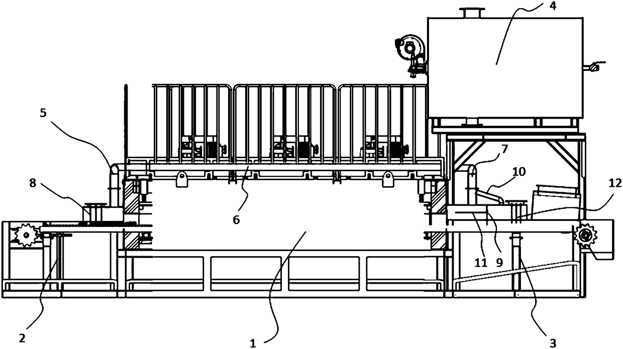
[0013] Such as figure 1 As shown, in a specific embodiment, the powder metallurgy tempering furnace of the present invention includes a tempering furnace body 1, a feed frame 2, a discharge frame 3, an incineration device 4, a fume collection pipe 5 at the feed port, and a fume collection main pipe 6 And the oil fume collection pipe 7 at the discharge port.

[0014] The feeding frame 2 is arranged on the side of the feeding port of the tempering furnace body 1 , and the discharging frame 3 is arranged on the side of the discharging port of the tempering furnace body 1 . The feed frame 2 is provided with a fume collection chamber (not shown) at the feed port, and one end of the fume collection chamber is connected through the feed port of the tempering furnace body 1 . The discharge frame 3 is provided with a fume collection chamber at the discharge port (not shown), and one end of the fume collection chamber at the discharge port is connected through the discharge port of the...


PUM


Abstract

The invention discloses a powder metallurgy tempering furnace. The powder metallurgy tempering furnace comprises a tempering furnace body. A feeding rack is arranged at a feeding inlet of the tempering furnace body, and a discharging rack is disposed at a discharging outlet of the tempering furnace body. The powder metallurgy tempering furnace further comprises a feeding inlet oil fume collecting chamber, a discharging outlet oil fume collecting chamber, an oil fume collecting header pipe and an incinerator, wherein one end of the feeding inlet oil fume collecting chamber is in through connection with the feeding inlet of the tempering furnace body; one end of the discharging outlet oil fume collecting chamber is in through connection with the discharging outlet of the tempering furnace body; one end of the oil fume collecting header pipe is in through connection with the feeding inlet oil fume collecting chamber through a feeding inlet oil fume collecting pipe, and the other end of the oil fume collecting header pipe is in through connection with the discharging outlet oil fume collecting chamber through a discharging outlet oil fume collecting pipe 7; and the incinerator is in through connection with the oil fume collecting header pipe. By means of the powder metallurgy tempering furnace provided by the invention, oil fume generated in the tempering process can be collected to the incinerator so that incineration disposal of the oil fume can be achieved, and environmental pollution caused by the tempering process is effectively reduced.

Description

technical field [0001] The invention relates to the field of waste gas treatment, in particular to a powder metallurgy tempering furnace. Background technique [0002] At this stage, with the maturity and development of powder metallurgy technology, more and more workpieces are gradually realizing powder metallurgy. Powder metallurgy parts will use lubricating oil in the pressing and forming process, and quenching oil will be used in the quenching process. Unlike non-powder metallurgy parts, due to the physical characteristics of powder metallurgy parts, it is difficult to remove most of the oil fume by cleaning and drying, which directly causes a large amount of oil fume to be generated during the heat treatment process. In the past, tempering furnaces suitable for heat treatment of non-powder metallurgy parts faced problems such as difficulty in collecting and disposing of oil fume, which directly led to excessive concentration of oil fume in the production workshop and s...

Claims


Application Information

Patent Timeline
Patent Type & Authority Patents(China)
IPC IPC(8): C21D1/18C21D9/00B22F3/24
CPCB22F3/24B22F2003/248C21D1/18C21D9/0068
Inventor 解冰寒沈顺飞韩伯群姜丰
Owner TIANJIN FENGDONG CHENXU METAL TECHNOLOGY CO LTD
Learn More