
Driver controller based on Ethernet control

A driver controller, Ethernet technology, applied in the direction of signal indicators, locomotives, climate sustainability, etc. on the vehicle, can solve the problem of not having the Ethernet communication capability of the on-board system, and achieve a small footprint and achieve intelligent the effect of

Active Publication Date: 2017-05-10
西安沙尔特宝电气有限公司
View PDF5 Cites 6 Cited by
  • Summary
  • Abstract
  • Description
  • Claims
  • Application Information

AI Technical Summary

Problems solved by technology

[0003] The purpose of the present invention is to solve the problem that the existing train driver controller does not have the ability to communicate with the on-board system through Ethernet, and to provide a driver controller based on the Ethernet communication protocol for data transmission

Method used


Image

  • Driver controller based on Ethernet control
  • Driver controller based on Ethernet control
  • Driver controller based on Ethernet control

Examples


Embodiment Construction

[0014] Below in conjunction with accompanying drawing and embodiment the present invention is described in further detail:

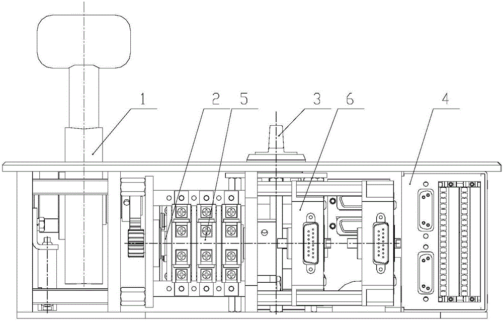
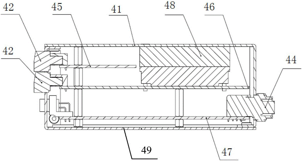
[0015] Such as figure 1 As shown, a driver controller based on Ethernet control includes a control handle assembly 1, a cam assembly 2, a direction switch 3, a snap switch 5, a photoelectric encoder 6 and an Ethernet controller 4. The control handle assembly 1 is provided with four gears for traction, an inertia position, seven gears for braking and an emergency braking position, and the control handle is integrated with a vigilance button device. Direction switch 3 is provided with " front ", " 0 ", three stalls of " back ". The driver controller uses the output signal of the snap switch 5 to judge the current handle position and provides the handle status bit information to the Ethernet controller 4, and uses the 10-bit Gray code signal output by the photoelectric encoder 6 to provide the traction brake level command and send the Ethernet The network...


PUM


Abstract

The invention relates to the field of rail transit locomotive vehicle control electric appliances, in particular to a driver controller based on Ethernet control to solve the problem that an existing driver controller is incapable of carrying out Ethernet communication with a vehicle system. The driver controller comprises a control handle assembly, a cam assembly, a direction switch, quick-action switches, optical-electricity encoders and an Ethernet controller. The Ethernet controller comprises a shell assembly, first connectors, second connectors, a third connector, a signal conditioning circuit board assembly, a power supply circuit board assembly and a control circuit board assembly. The first connectors are connected with the quick-action switches; the signal conditioning circuit board assembly and the power supply circuit board assembly are connected with the first connectors; the second connectors are connected with the optical-electricity encoders; the control circuit board assembly is connected with the second connectors; the signal conditioning circuit board assembly and the power supply circuit board assembly are both connected with a single chip microcomputer; and the third connector is in communication with an upper computer. The driver controller based on Ethernet control is used for rail locomotives, motor train units and the like.

Description

technical field [0001] The invention relates to the field of rail transit locomotive vehicle control appliances, in particular to a driver controller based on Ethernet control. Background technique [0002] The driver controller is the control equipment for rail locomotives, EMUs and industrial automation, and is the master electrical appliance for locomotive commutation and speed regulation. With the development of technology and the improvement of the needs of passengers and operators, the network of urban rail vehicles needs to transmit more and more information. The traditional train network MVB cannot support such a large amount of data, so Ethernet began to be applied in urban rail on the vehicle. Compared with the traditional train communication network, Ethernet has higher bandwidth for data transmission and stronger compatibility. However, driver controllers on existing trains do not have the ability to communicate via Ethernet with on-board systems. Contents of...

Claims


Application Information

Patent Timeline
Patent Type & Authority Applications(China)
IPC IPC(8): B61C17/00B61L15/00
CPCB61C17/00B61L15/0018Y02T30/00
Inventor 周倩马昌峰郑怿王重阳刘跃鸣
Owner 西安沙尔特宝电气有限公司
Learn More