Novel hand screw clamp

A woodworking clip, a new type of technology, applied in the direction of clamps, manufacturing tools, etc., can solve the problems of fracture, large wear of the handle screw, poor load capacity, etc., and achieve the effect of stable structure, uniform fixed force, and long service life

Inactive Publication Date: 2017-05-10
TIANJIN BAOLITONGDA TOOL CO LTD
View PDF0 Cites 2 Cited by
  • Summary
  • Abstract
  • Description
  • Claims
  • Application Information

AI Technical Summary

Problems solved by technology

[0004] The F-type carpentry clips in the prior art have poor load capacity, and will break due to over-limit pressure during use, and the handle screw will wear a lot during use.

Method used


Image

  • Novel hand screw clamp
  • Novel hand screw clamp

Examples


Embodiment Construction

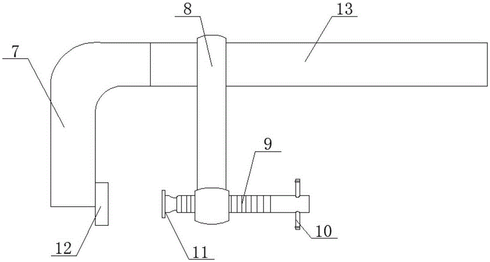
[0022] Specific embodiments of the present invention are described below in conjunction with accompanying drawing:

[0023] Such as figure 2 As shown, the present invention provides a novel woodworking clamp, comprising a second fixed arm 7 and a second guide rod 13 forming an L-shaped structure, the second guide rod 13 is slidably connected with a second movable arm 8, and the second movable arm 8 The other end of the threaded hole is provided with a threaded hole, the threaded hole is connected with a screw 9, the upper end of the screw 9 is connected with a second lower pressing block 11, the other end is provided with a through hole, and the through hole is connected with a metal screw handle 10, the second fixed A second upper pressing block 12 is connected below the arm 7 .

[0024] The second fixed arm 7 and the second guide rod 13 are integrally formed of steel materials, and the connection between the second fixed arm 7 and the second guide rod 13 is a 90-degree ben...


PUM


Abstract

The invention provides a novel hand screw clamp and belongs to the technical field of clamps. The novel hand screw clamp comprises a second fixed arm and a second guide rod which form an L-shaped structure, wherein a second movable arm is glidingly connected onto the second guide rod, a threaded hole is formed in one end of the second movable arm and connected with a screw, the upper end of the screw is connected with a second lower press block, a through hole is formed in the other end, a metal screw rod rotating handle is connected to the through hole, and a second upper press block is connected to the lower part of the second fixed arm. Compared with the prior art, the second fixed arm and the second guide rod are integrally bent to be formed, an all-steel structure is adopted, the steel body load can be exerted to the maximum strength by means of 90-degree bending, larger clamping force can be borne in a use process, and breaking of a traditional dual-component F clamp due to exceeding of limit pressure is avoided.

Description

technical field [0001] The invention relates to the technical field of clamps, in particular to a novel woodworking clamp. Background technique [0002] Woodworking clips are also called F clips, such as figure 1 As shown, it includes a first guide rod 6, one end of which is fixedly connected with a first fixed arm 1, a first movable arm 2 is set on the body of the rod, and a first handle screw 3 is installed near one end of the movable arm. The first lower pressing block 4 is loosely installed, and the first upper pressing block 5 is formed on one end corresponding to the lower pressing block of the fixed arm. The bottom of the first guide rod 6 has a hexagonal hole, and the bottom of the first guide rod 6 The lower end is provided with a bayonet, which is used to prevent the first guide rod 6 from slipping. [0003] How to use the F-type woodworking clamp: slide the first movable arm 2 by hand, the first movable arm 2 must be kept parallel to the first guide rod 6 when s...

Claims


Application Information

Patent Timeline
Patent Type & Authority Applications(China)
IPC IPC(8): B25B5/10B25B5/16B25B5/02
CPCB25B5/102B25B5/02B25B5/163
Inventor 刘志平
Owner TIANJIN BAOLITONGDA TOOL CO LTD
Why Eureka
Try Eureka